Installation
1
Remove engine access panel and knee panel on the left side of the hull.
2
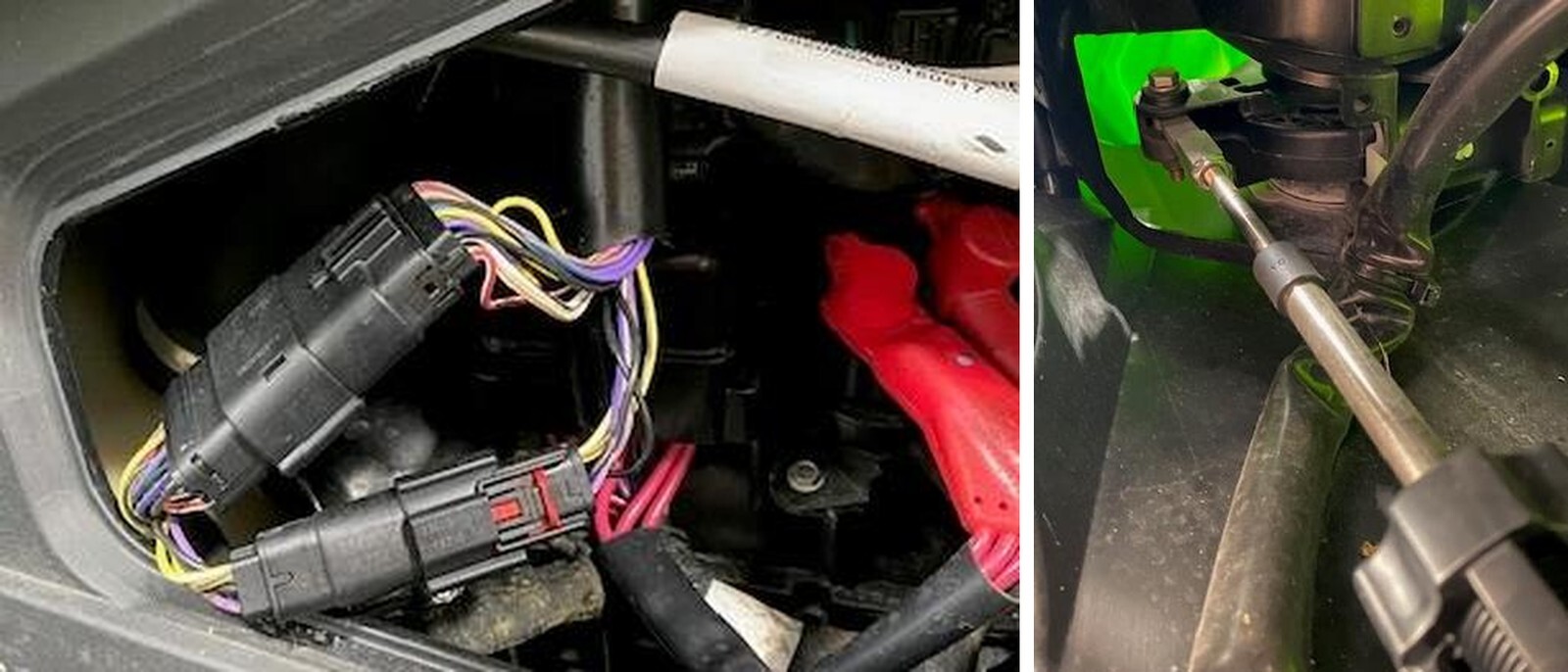
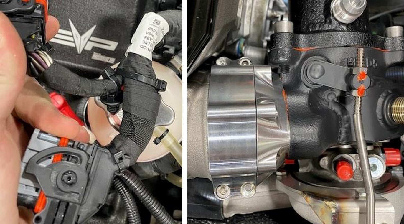
Through the engine access panel, disconnect the steering control (20 pin) plug and if equipped IBR (6 pin) plug. Do not use a screwdriver to pry off.
3
Underneath the handlebars, through the knee panel you will locate the steering linkage. Remove the linkage with (2) 10mm sockets. Remove the steering linkage brace by removing (2) T30 head screws.
4
Once the steering linkage is loose, push it into the engine bay.
5
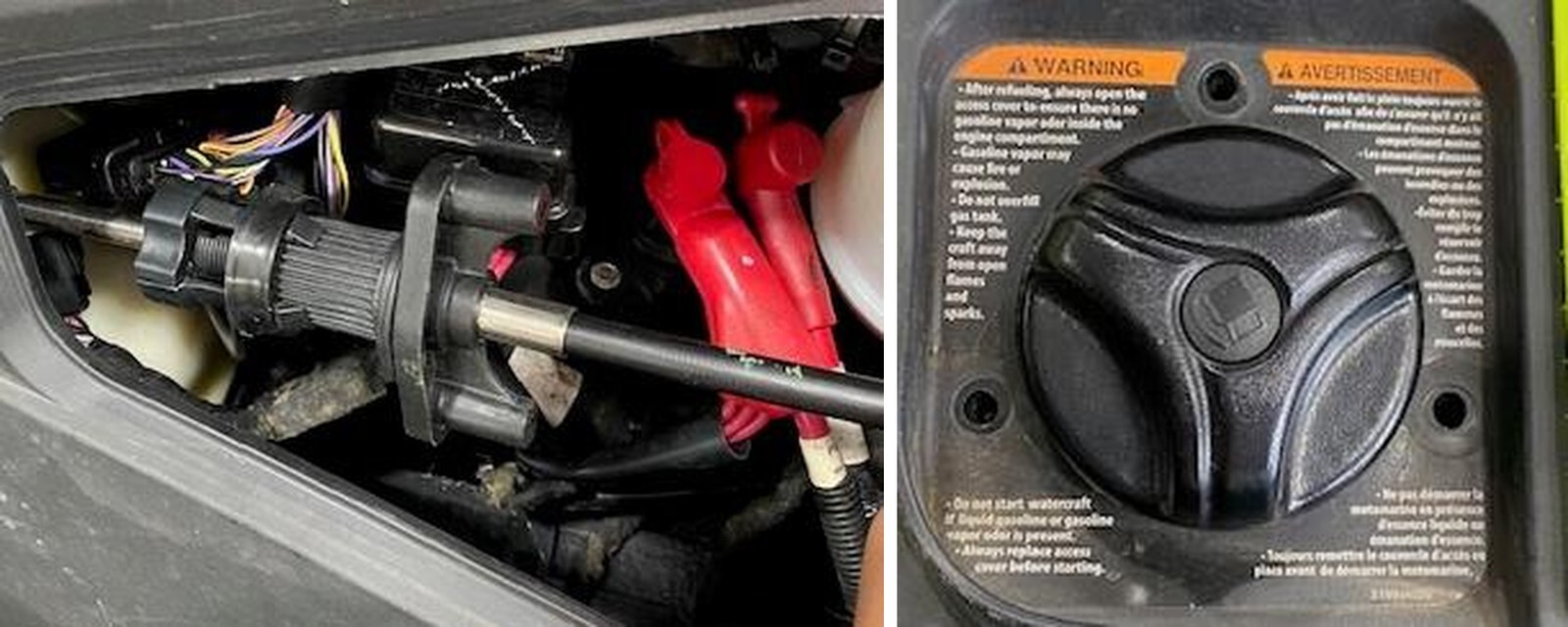
Remove the seat. Remove the (3) T30 screws around the fuel fill. Leave cap on.
6
With a T30 socket, remove 23 screws holding the upper hull (black portion) on. (10) screws have a locknut underneath the lower hull. Use a 10mm socket.
1
Make sure the battery terminals are disconnected.
2
Remove the water box, (2) worm drive clamps and coupler from exhaust manifold to water box, (1) worm drive from water box to “J” pipe, (1) connector for exhaust temperature sensor, (1) zip tie holding the bilge pump connector.
3
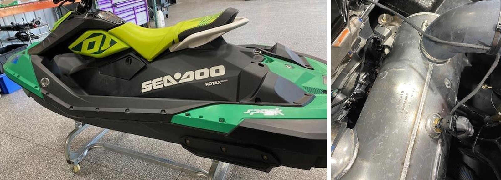
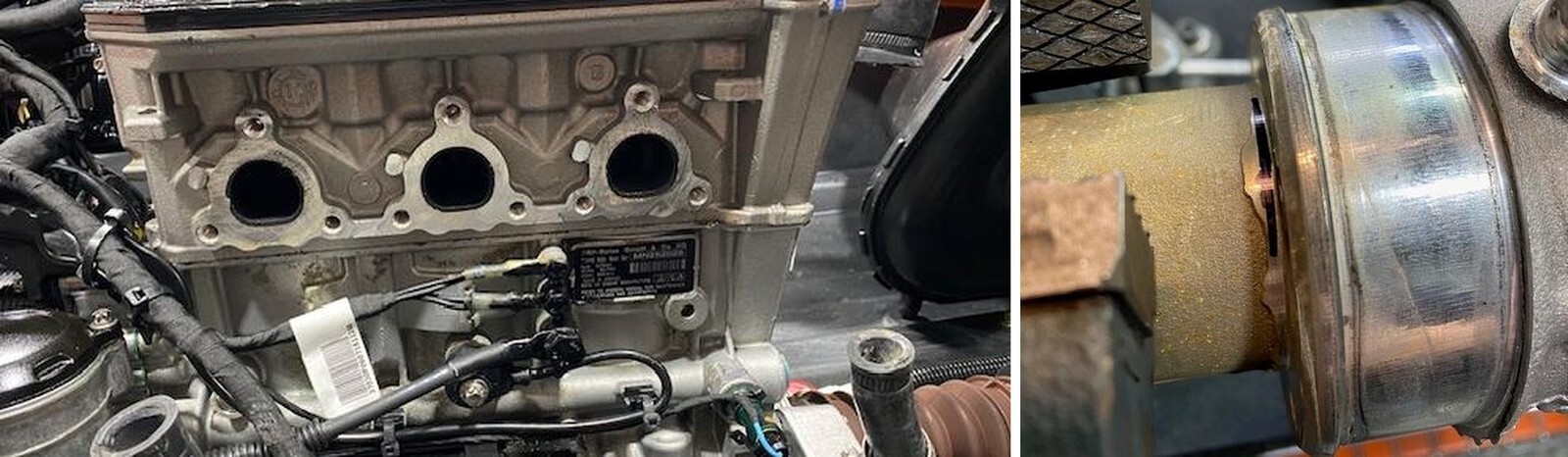
Remove the exhaust manifold. Loosen (2) worm drives for water in/out and (9) manifold screws using an E10 socket.
4
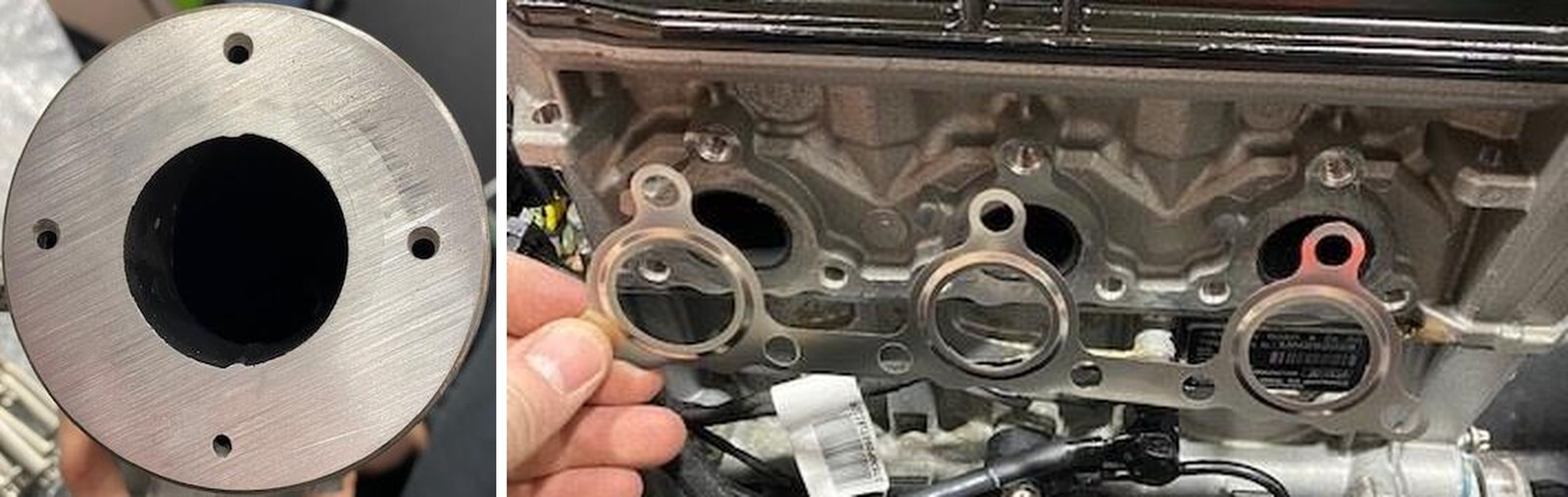
Place the exhaust manifold in a vice. Cut the 2.0” steel pipe off at the lip. See marking. Next file/sand the lip completely off. Test fitment in the turbocharger billet connector.
5
Reinstall the exhaust manifold with supplied gasket. Torque bolts to 17 ft lbs.
6
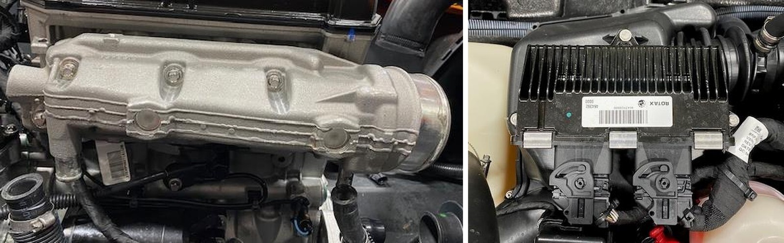
Remove the ECU, (3) 7mm screws and (2) ECU header connectors.
7
Remove the starter solenoid by removing (2) 7mm screws. Remove the fuse block by squeezing (2) clips together.
8
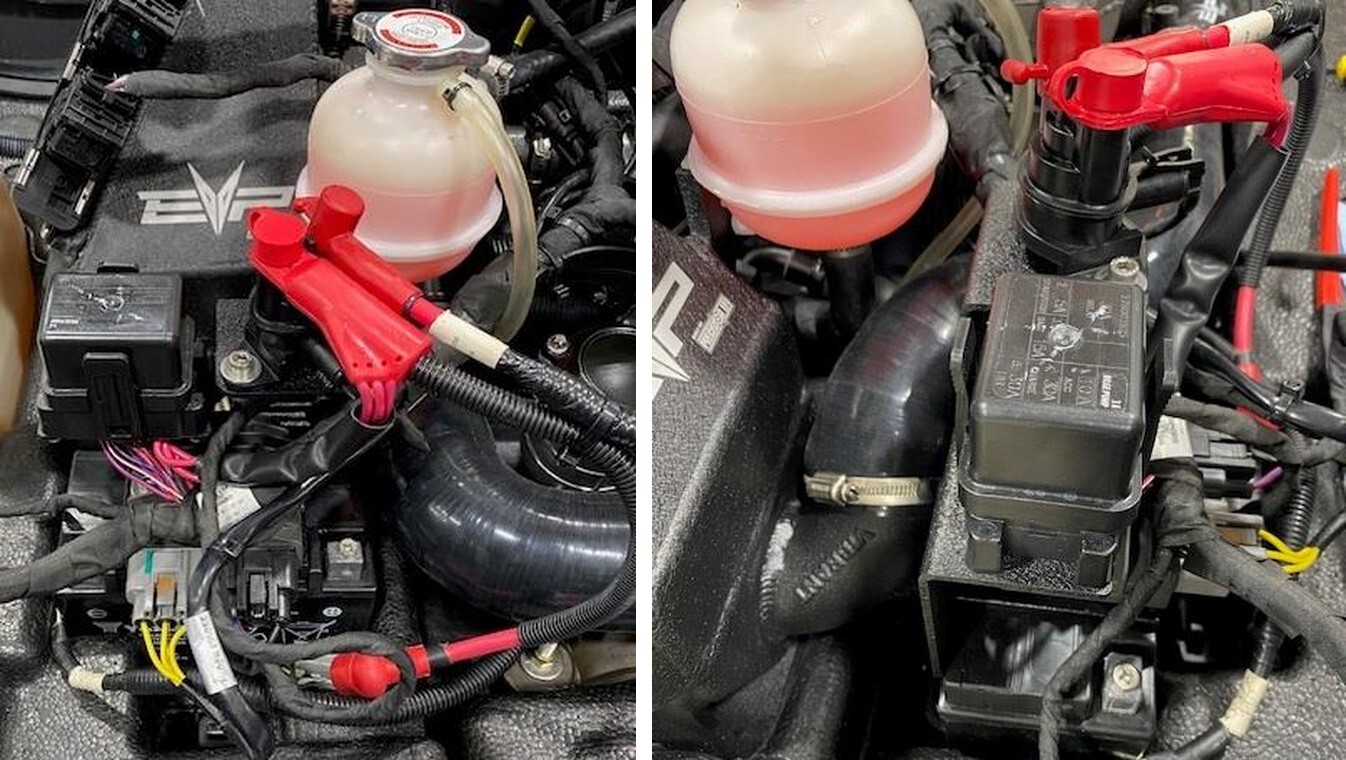
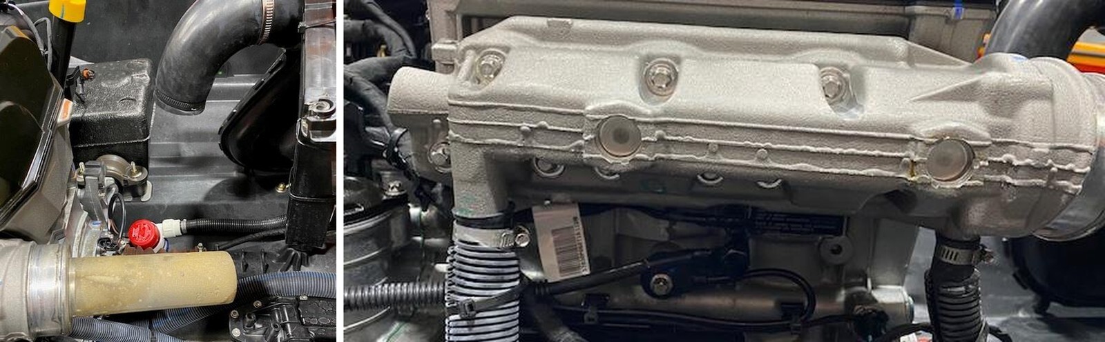
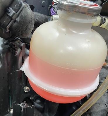
Remove the coolant reservoir by removing (1) 7mm screw and (1) clip on backside.
9
Remove the T-30 screw holding the valve cover fitting on. Reinstall the T30 screw loosely.
10
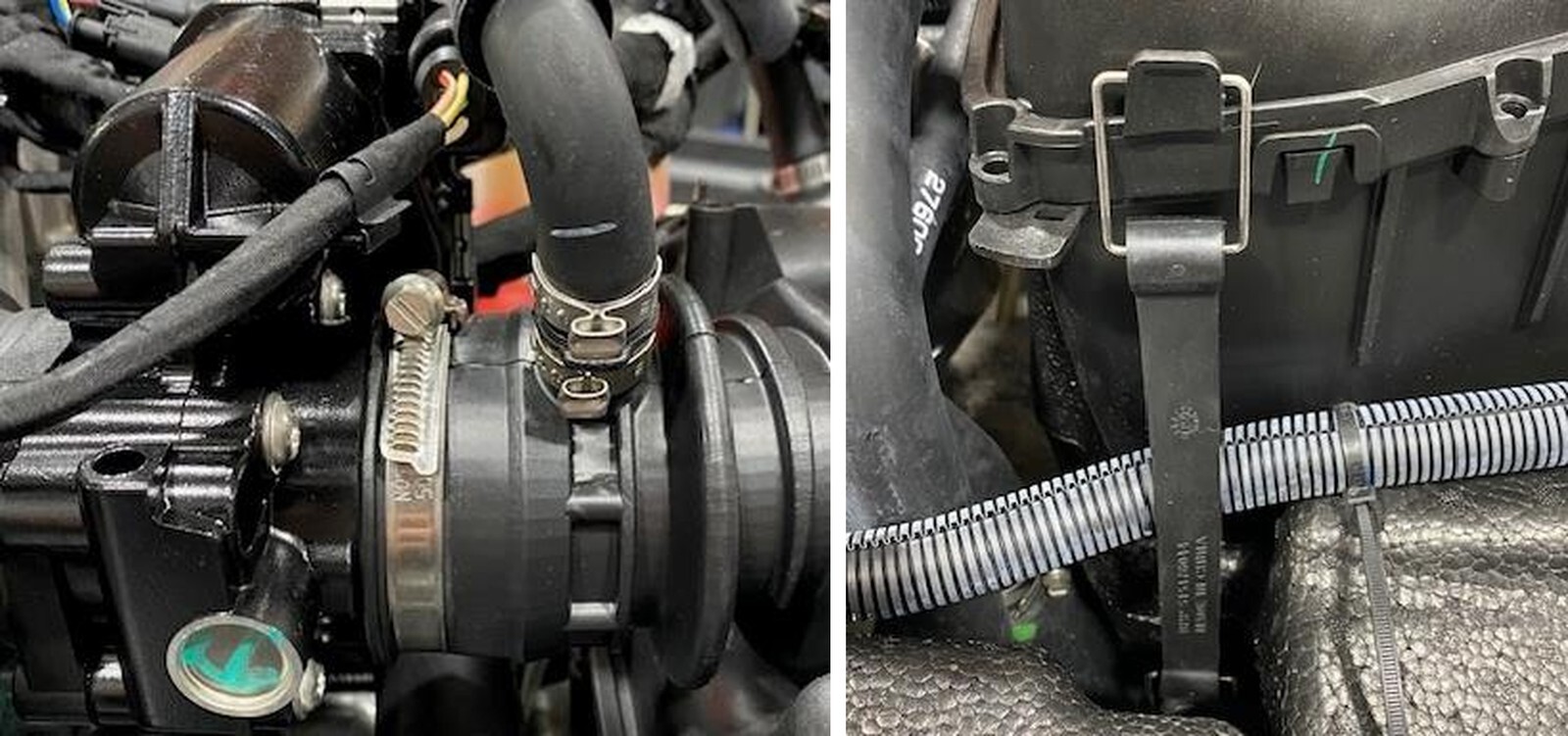
Remove the worm drive holding the intake boot onto the throttle body.
11
Remove (2) airbox straps, one of each side.
12
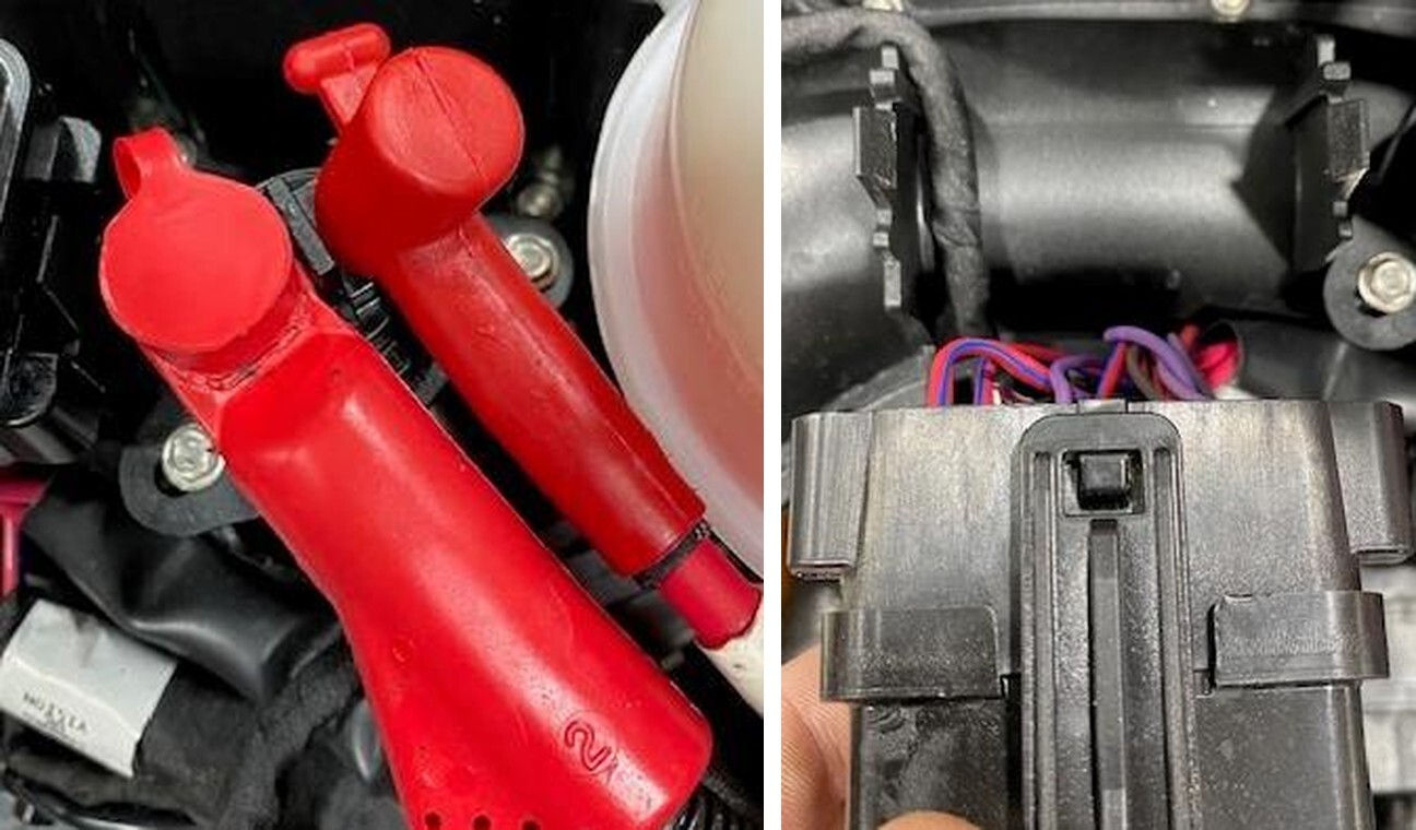
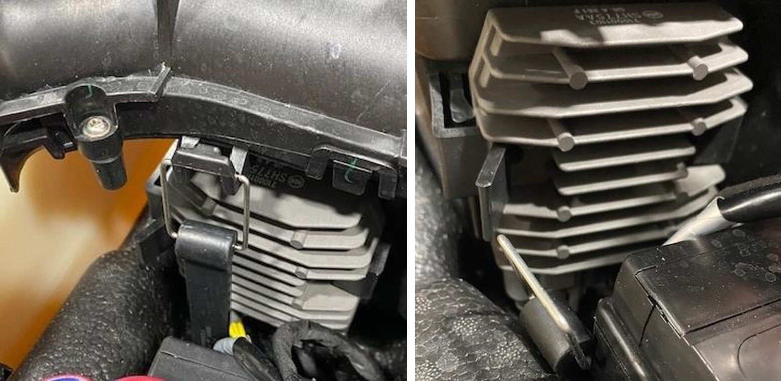
Remove the voltage regulator by pressing down on the clip. Unplug both black and grey connectors from the voltage regulator. Place to the side for now.
13
Remove the diagnostic port and let dangle for now.
14
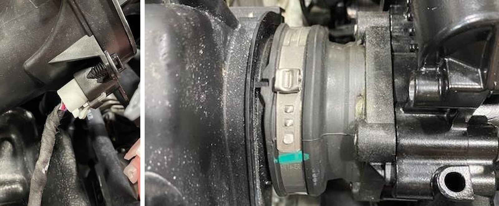
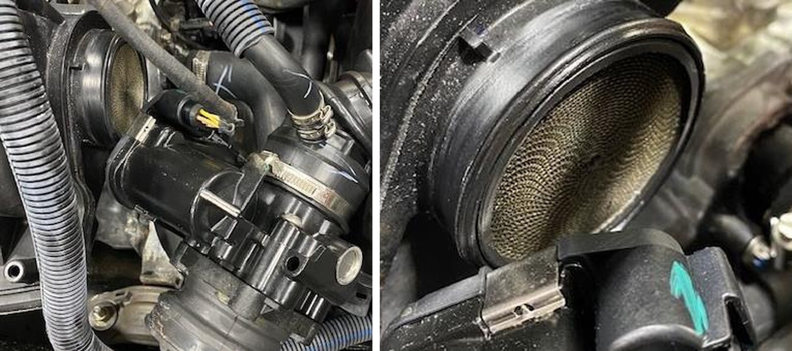
Remove the pinch clamp from the throttle body boot to plenum. Discard.
15
Pull the throttle body boot off the plenum. Located in the plenum is the flame arrestor.
16
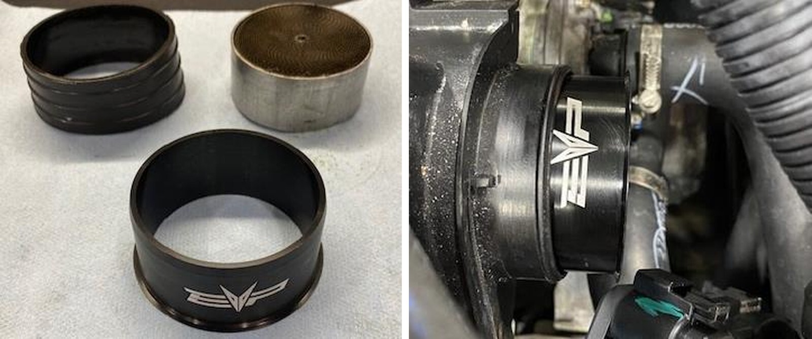
Remove the flame arrestor and seal.
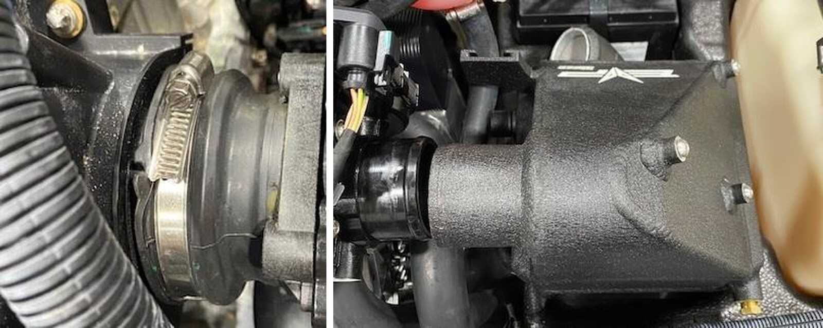
17
Install the ribbon delete into the plenum until it bottoms out. Reinstall the throttle body boot and supplied clamp. No seal, use supplied 60-80 worm drive clamp. Install (2) zip ties holding the fuel hose to plenum.
18
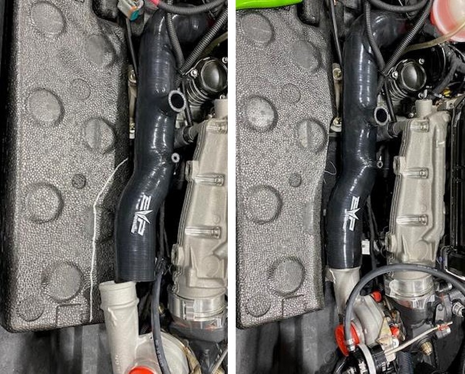
Install the intercooler where the airbox was located, make a mark around the inlet pipe because this foam will need to be tripped. Make it large enough for silicone and a clamp.
19
Install the 2.25” x 3.0” coupler between the intercooler exit and throttle body. Use (2) 32 constant tension clamps.
20
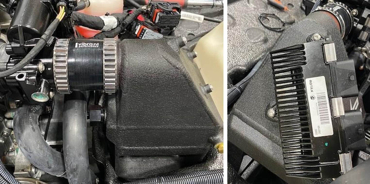
Install the ECU onto the front of the intercooler, use supplied M6 screws. Cut the zip tie holding the two ECU connectors together. Connect to ECU.
21
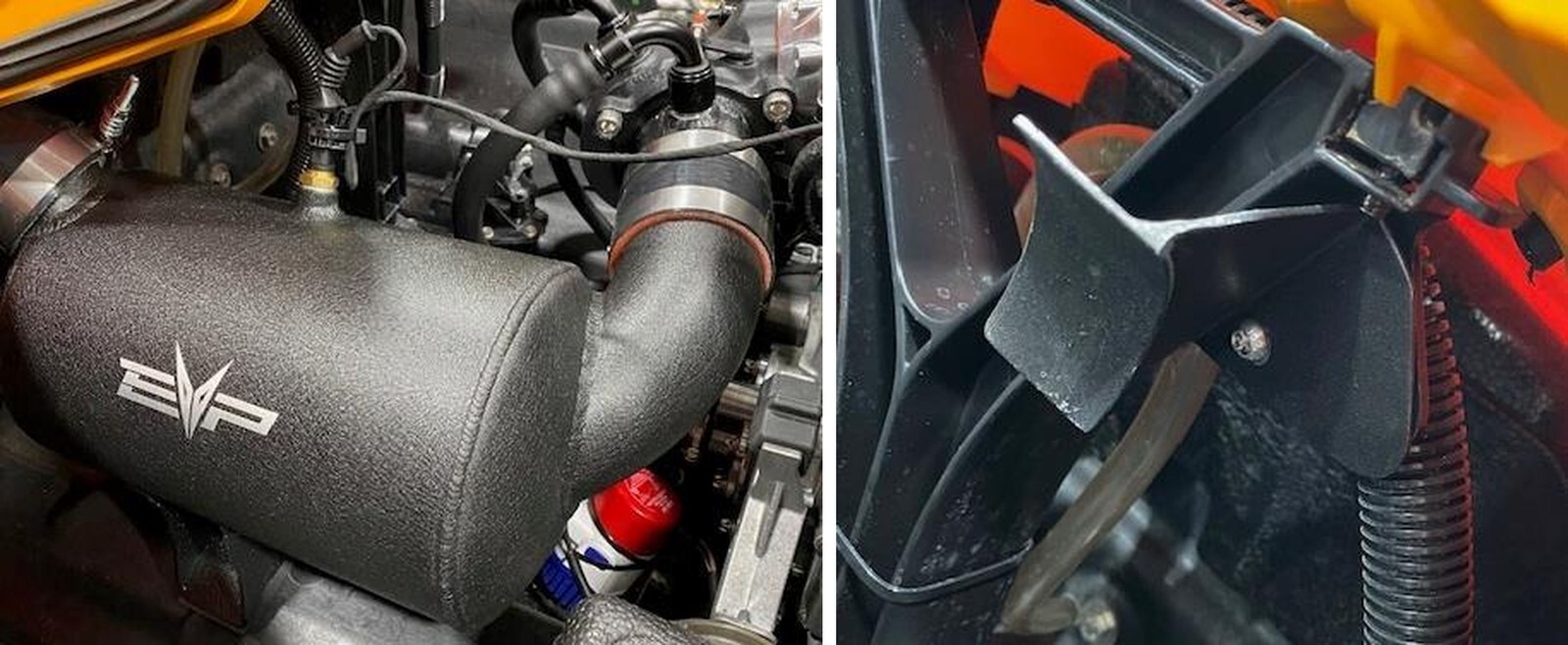
Loosely mount the turbocharger to the exhaust manifold. You can see the compressor housing will touch the foam.
22
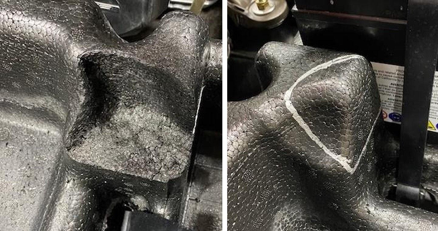
Install the charge tube from the intercooler to turbocharger. They won’t align perfectly. With a sharpie outline the turbocharger and charge tube. Cut the foam at a 45-degree angle. Test fit as you go.
23
Locate the water pickup to intercooler hose, (1) 10AN 90 degree fitting and (1) “T”.
24
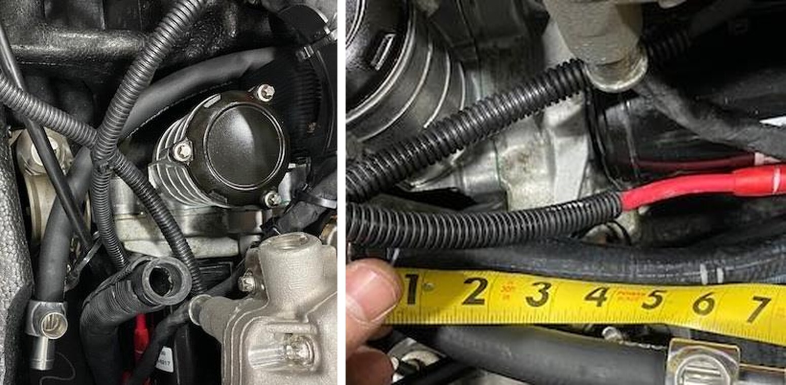
Install the 10AN 90 degree fitting onto the intercooler, route the “T” around the oil filter housing towards the exhaust manifold. Locate the water pickup hose that was connected to the exhaust manifold (left side). Cut 5-3/4” off the hose. Cut 7.0” of sleeving off.
25
The hose you just cut, cut it down to 3-1/2” in length.
26
Install the water pick up hose to the right side of the “T” fitting. Install the 3-1/2” hose to the top of the “T” fitting. Install the 7.0” of sleeving onto the hose going to the intercooler. Clamp all hoses to the “T” with supplied 16-25mm worm drive. Clamp the top hose to the exhaust manifold reusing the OEM worm drive.
27
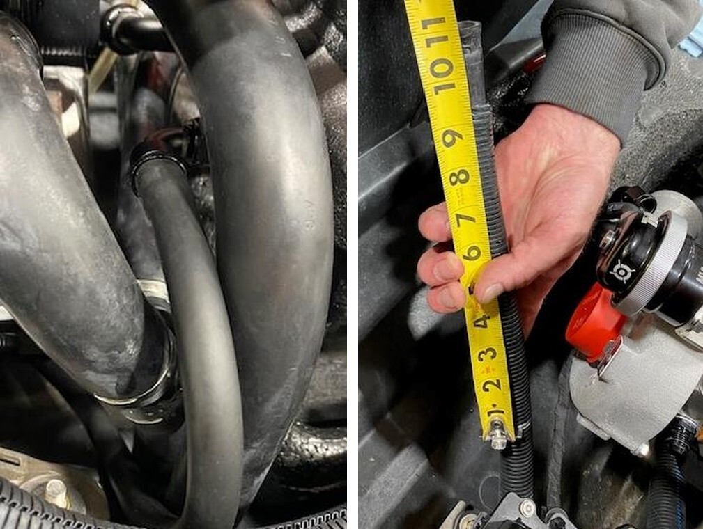
Locate the intercooler exit to turbocharger hose, 41” in length, (2) 6AN 90 Degree fittings. Install one fitting onto the intercooler exit and run underneath the engine back towards the turbocharger.
28
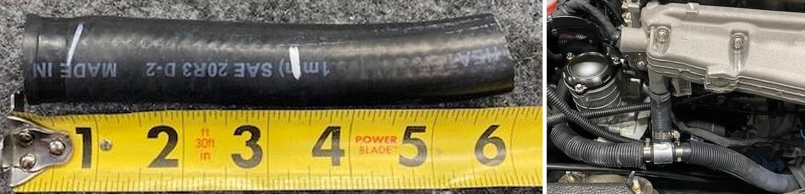
Locate the exhaust manifold exit hose, cut 11.00” of hose off and 9.0” of sleeving off.
29
Locate the 7.0” long 6AN hose with 6AN 90 Degree fitting and 3/8-1/2” coupler.
30
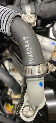
Install this hose to the exit hose, reuse OEM 16-27mm worm drive clamp.
31
You can remove the turbocharger and place it on a work bench. You are left with both inlet and exit water feed lines for the turbocharger.
32
If your spark is equipped with IBR system, remove the (3) 13mm head screws. The top left screw has a nyloc nut on the back. Do not lose the stainless-steel bushings.
33
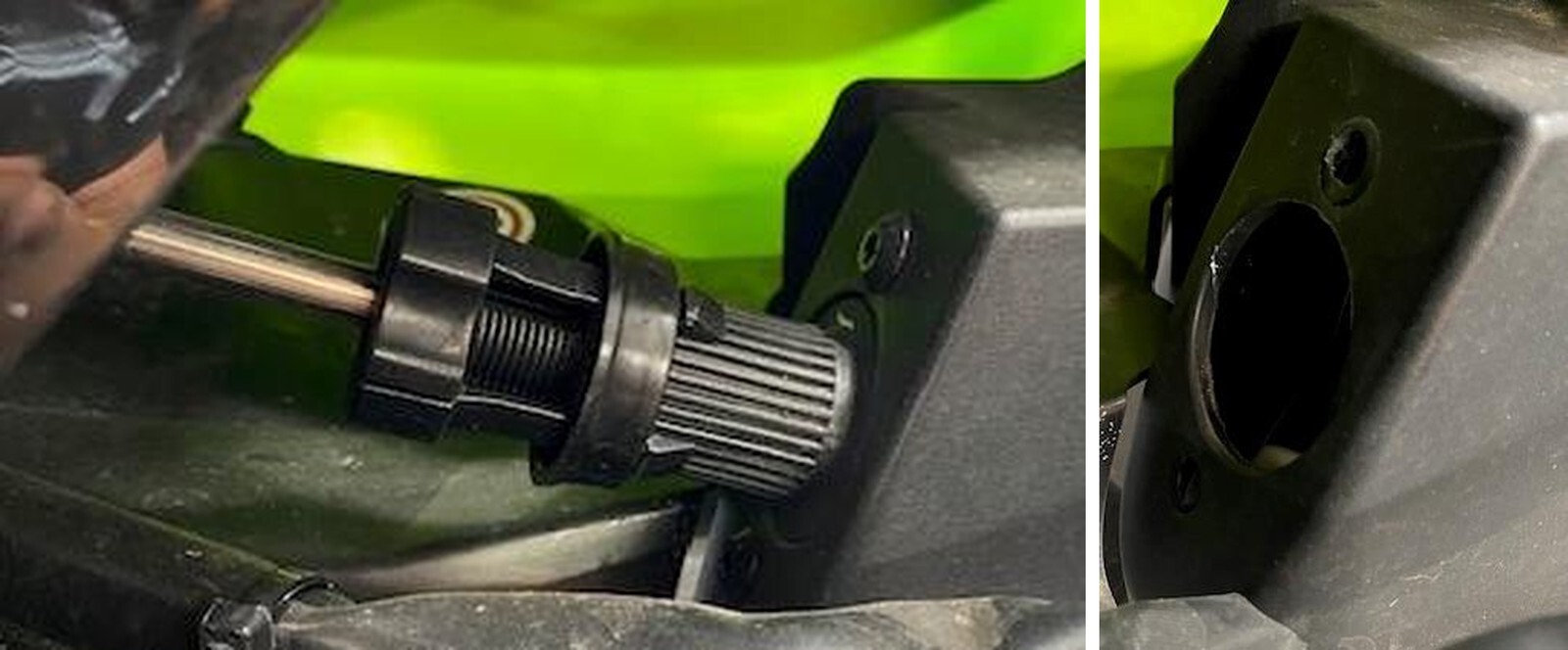
Turn the nozzle and remove the steering linkage. Use 2 10mm sockets.
34
With a 1/4" socket loosen the worm drive holding the siphon tube onto the jet pump. Remove the siphon tube.
35
With a 12” extension and swivel you can access the (3) jet pump screws.
36
Once hardware is removed, wiggle the jet pump out of the hull and driveshaft.
37
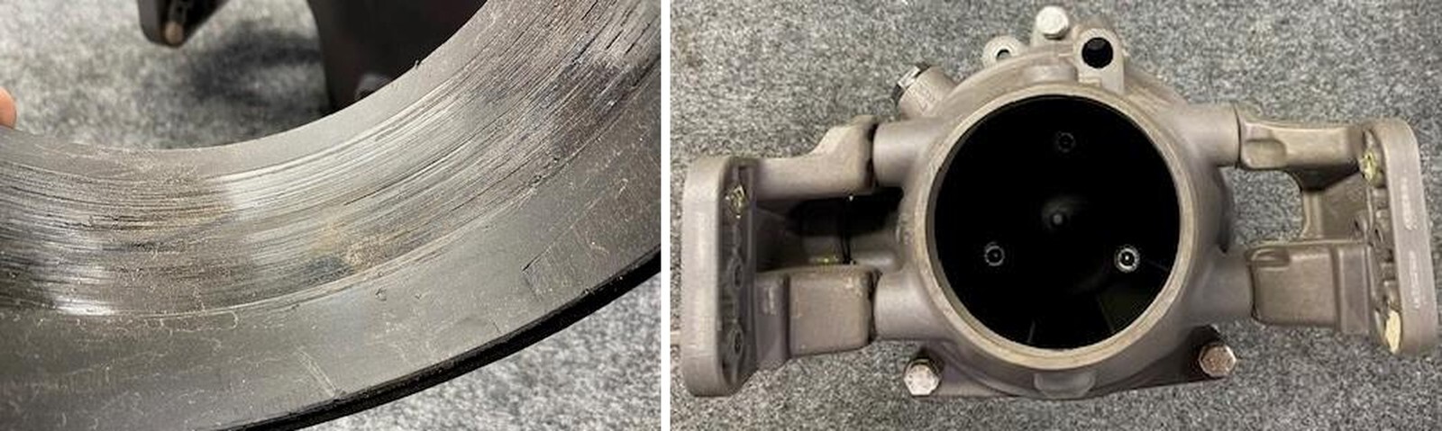
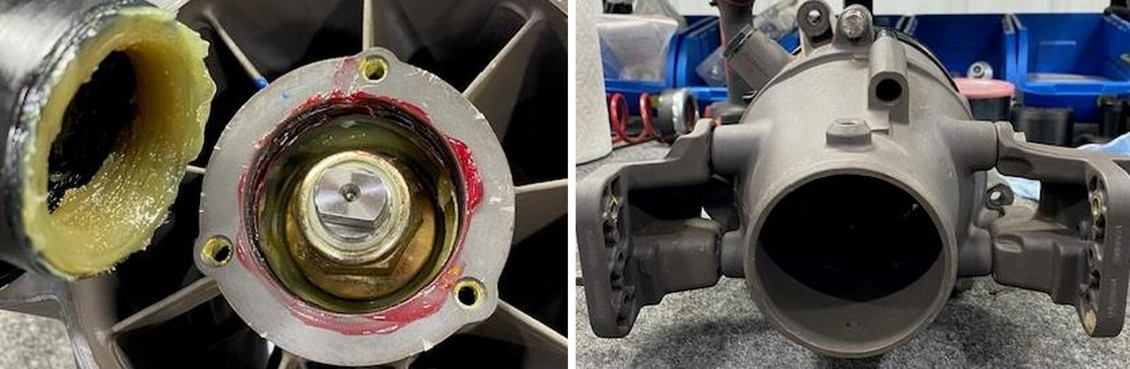
With the jet pump on a work area, remove and inspect the wear ring.
38
Loosen and remove the (3) venturi screws. Remove venturi from pump.
39
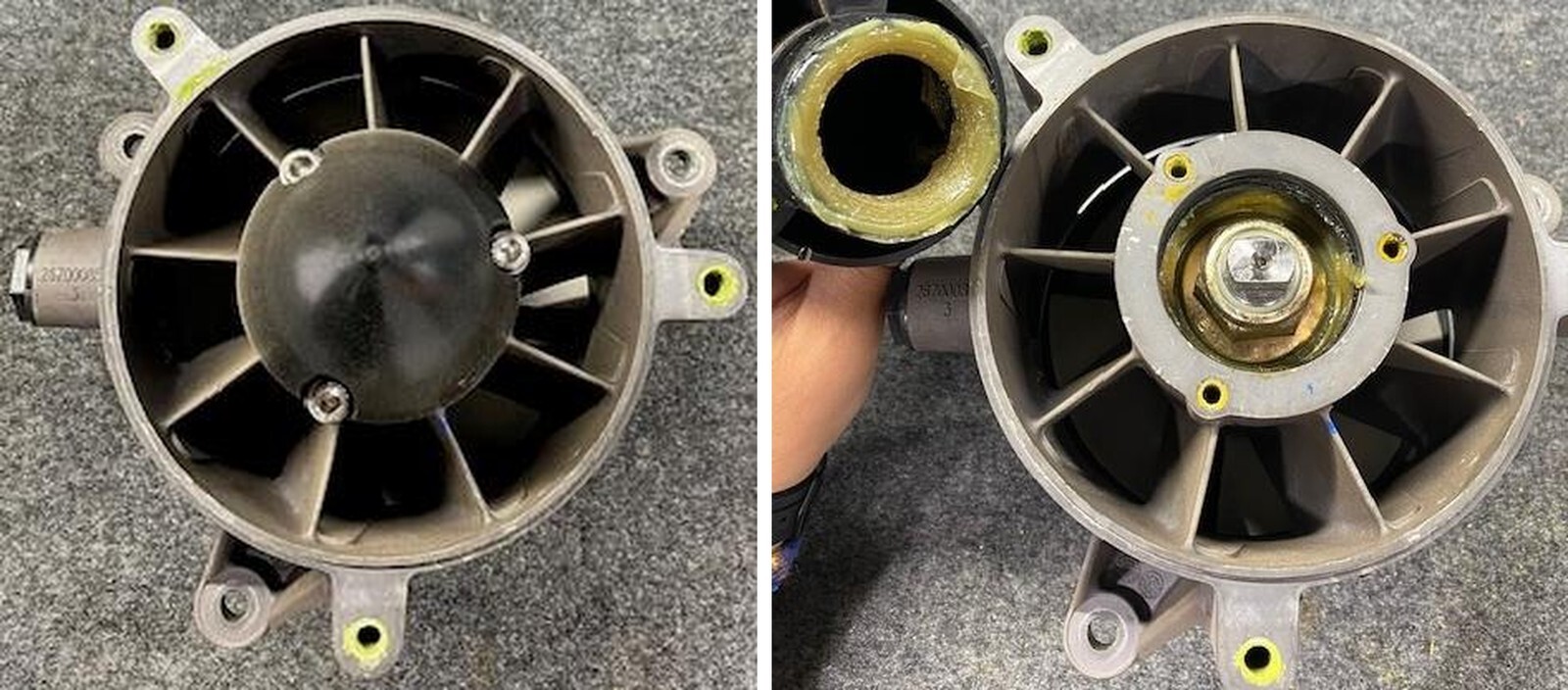
Remove the (3) Allen screws holding the impeller cone on. 5mm Allen.
40
Remove the impeller cone, you may need to pry with a screwdriver.
41
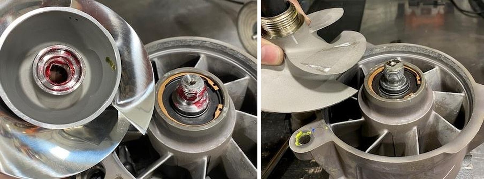
Install the two flat spots into a vice. Clamp tight. Install the impeller spline tool WR001 Into the impeller. Loosen the impeller with a breaker bar. Spin the impeller off.
42
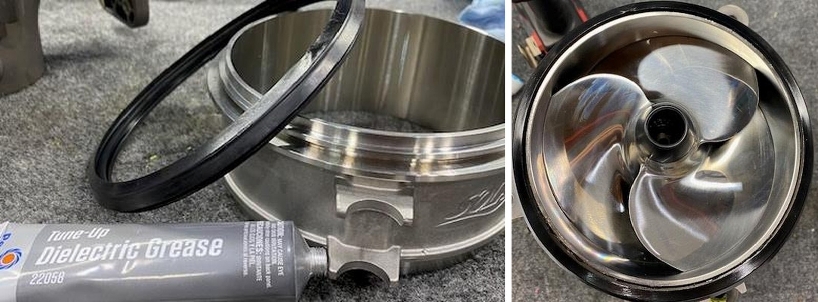
With the impeller removed, grease up the jet pump shaft, threads and new impeller O- ring and threads.
43
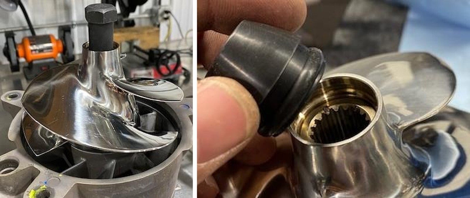
Install the new impeller and spine onto the jet pump threads. Install the spline tool and torque down to 92 ft-lbs.
44
Remove the spline tool, grease the impeller splines and rubber boot. Install the rubber boot.
45
Grease the bottom of the jet pump, o rings and cone. Reinstall the cone. Torque screws to 80 in-lbs and apply blue Loctite.
46
Reinstall the venturi onto the jet pump. Torque to 18 ft-lbs and apply blue Loctite to the threads.
47
Remove the OEM wear ring seal. Apply grease on the o ring and install onto the new stainless steel wear ring.
48
Apply a light amount of grease onto the inside of the wear ring and slide onto the jet pump. This helps for initial start up.
49
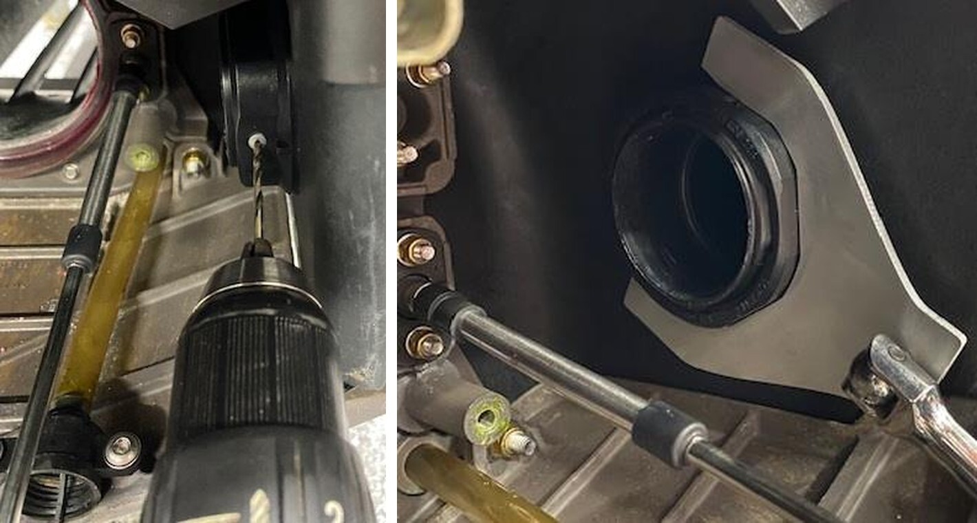
Drill out the rivet on the OEM exhaust piece. Use a 1/8” drill bit.
50
Use supplied exhaust nut wrench and loosen the nut.
51
Remove the OEM “J” pipe and muffler.
52
Extract out as much oil as possible through the dipstick tube.
53
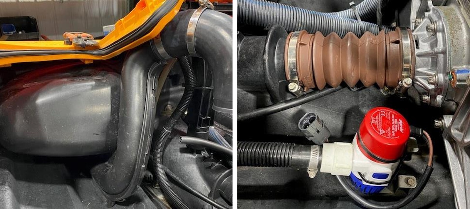
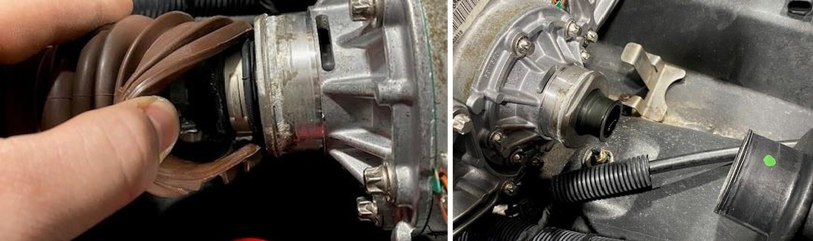
Loosen both worm drive clamps on the outer drive shaft boot.
54
Pull back on the outer brown boot, underneath is a pinch clamp around the inner boot. Cut this clamp.
55
It is best to lift the rear of the jet ski about 6.0”. Pull the driveshaft out of the hull. Place rags underneath the PTO cover and remove (6) PTO cover screws using a E10.
56
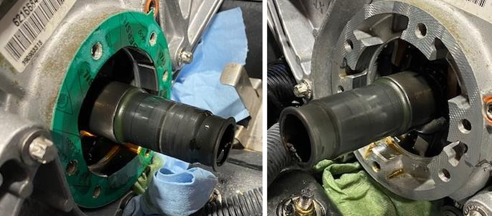
Remove the OEM PTO cover. Some oil will spill out.
57
Remove the old PTO gasket.
58
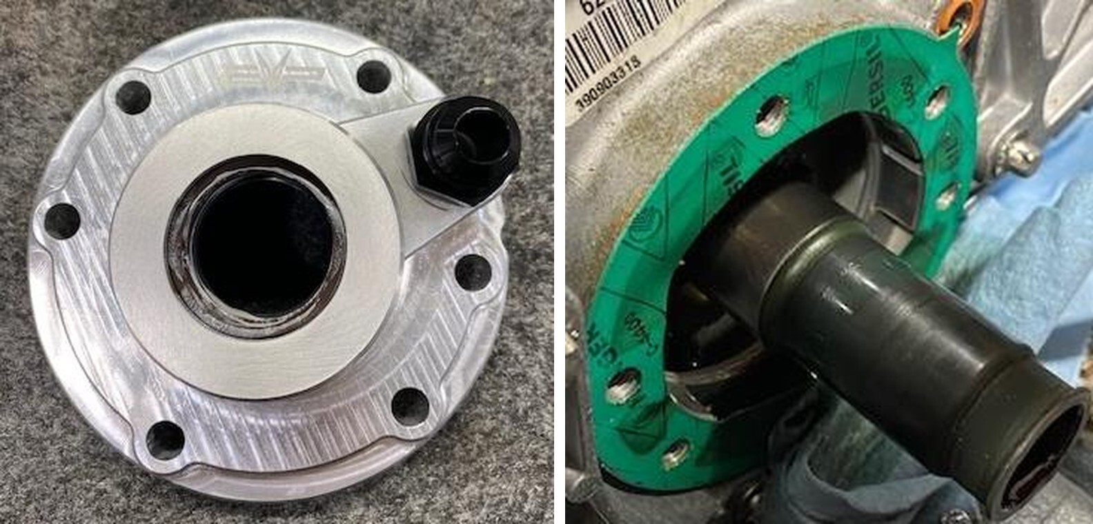
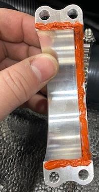
Locate your new PTO cover with 10AN fitting. 2014-2021 have a longer style PTO cover so these instructions might show a different PTO cover than a 2022+.
59
Install new supplied PTO gasket (words facing out) and PTO cover. Torque bolts in a cris-cross pattern to 17 ft-lbs.
60
Grease up the splines on the drive shaft and inner drive shaft boot. Slide a 36.1mm pinch clamp over the inner boot and reinstall the drive shaft. Grease should squeeze out. Pinch the clamp, reinstall the outer brown boot and worm drive clamps.
61
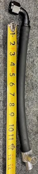
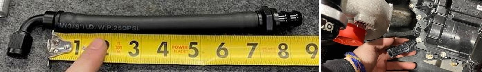
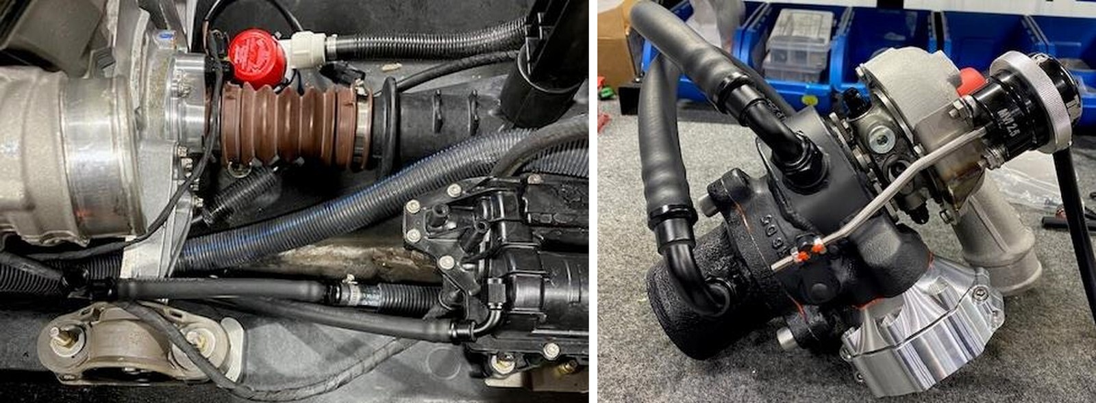
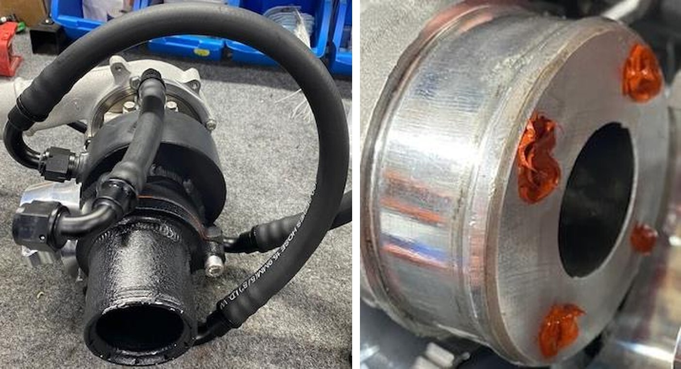
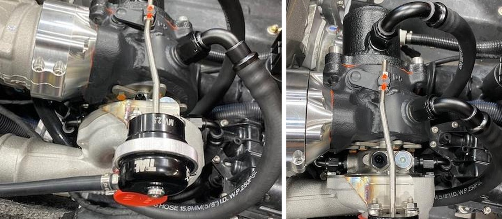
Install the turbocharger turbine housing inlet hose. 21” long with (1) 10AN 90 degree fitting to 1/2" adaptor. The opened end will get attached later.
62
Install the turbocharger turbine housing exit to exhaust hose. 18” long with (2) 120- degree 10AN fittings. Install the oil drain line (2) 90-degree fittings 5-3/4” long.
62
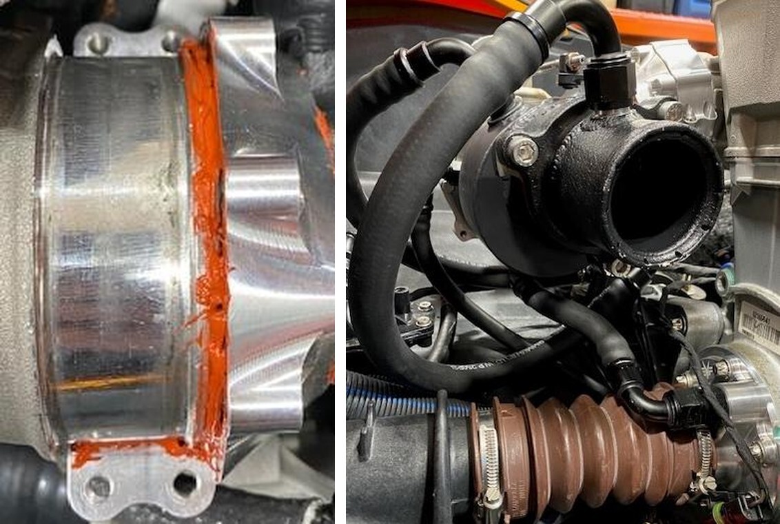
A: Apply a large amount of Permatex RTV, ultra red high temperature gasket maker to the (4) exhaust manifold water ports. Also run a thick bead on the outer lip of the billet connector.
63
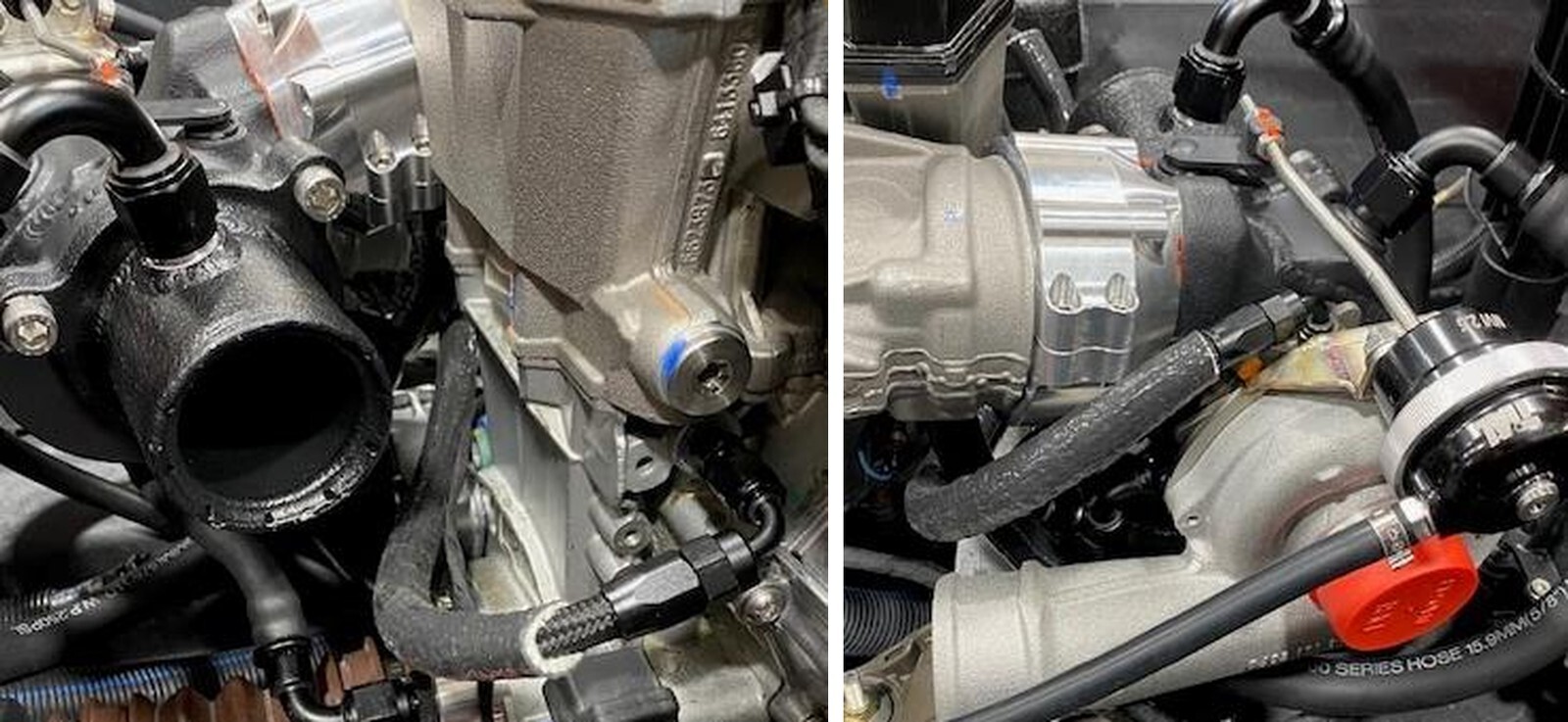
Install the turbocharger to the exhaust manifold loosely again, install the turbo oil drain line to the PTO cover. Clock the turbo if needed. Once this line is correct install all (7) M6 screws into the billet connector.
64
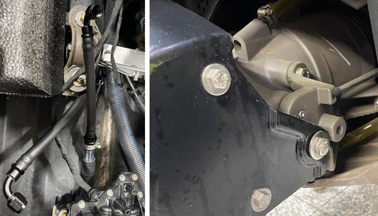
Install the turbocharger water inlet/exit hoses. Inlet coming from the intercooler line ran underneath the engine (right side), and the water exit leaving the hull (left side).
65
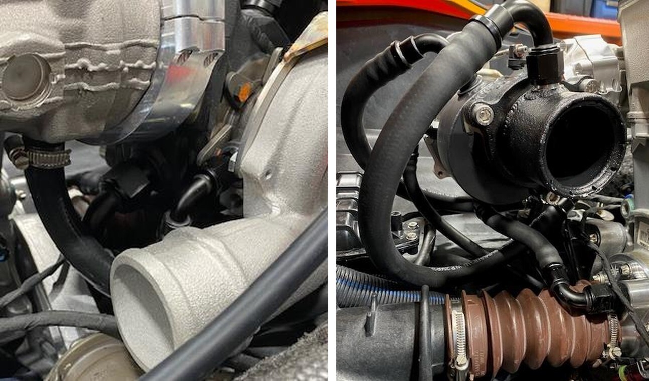
Install the turbine water line to the last port on the exhaust manifold. This hose reduces to 1/2" hose. Use 16-25mm worm drive clamp.
66
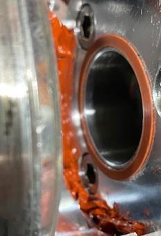
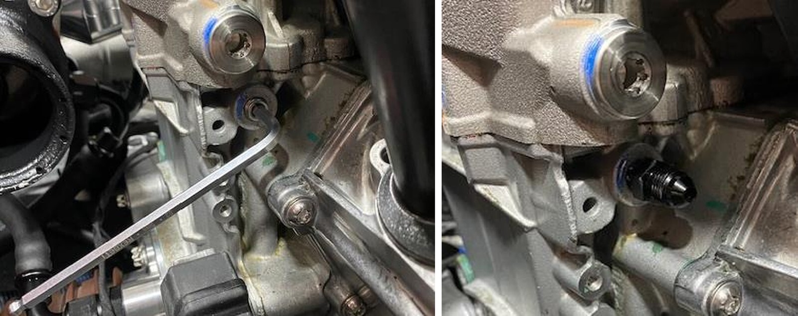
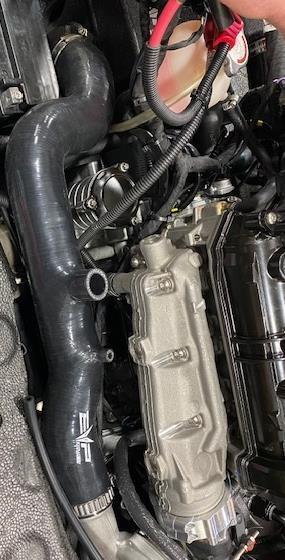
By the dipstick you will find an oil passage, remove the M6x1.0 plug.
67
Install supplied 1/8MPT to 4AN male fitting, make sure fitting is snug but not overtighten.
68
Install fire sleeve over the oil feed line. Blow out the line before install. Install one end to the fitting on the engine wrapped around to the turbocharger.
69
Now is a good time to go back through every hose and tighten all AN fitting’s. It is best to use aluminum AN wrenches so they don’t mar up the fittings. Double check routing and rubbing. Some fittings may need to be clocked a certain way so rubbing doesn’t accrue.
70
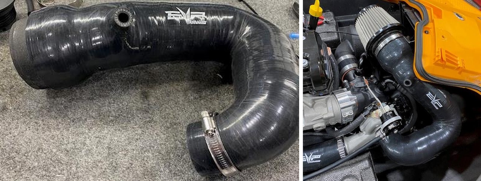
Install the charge tube from compressor housing to intercooler. Adjust the tube around the battery and the blow off valve port is facing upwards. Use a 60-80mm worm drive on the intercooler and 32 constant tension clamp on the turbo.
71
Remove the lower bracket on the electronics bracket. (2) 3mm Allen screws.
72
Install the voltage regulator onto the bottom electronics bracket, use supplied hardware. Place the battery strap underneath the voltage regulator. Reinstall the bottom bracket to the upper bracket using (2) 3mm screws.
73
Install the starter solenoid to the upper bracket using supplied hardware.
74
Install the fuse box onto the upper bracket using (4) screws.
75
Strap the battery in place, this will hold the electronics bracket as well. Reconnect the voltage regulator. Install the coolant jug onto the intercooler bracket.
76
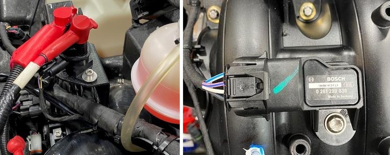
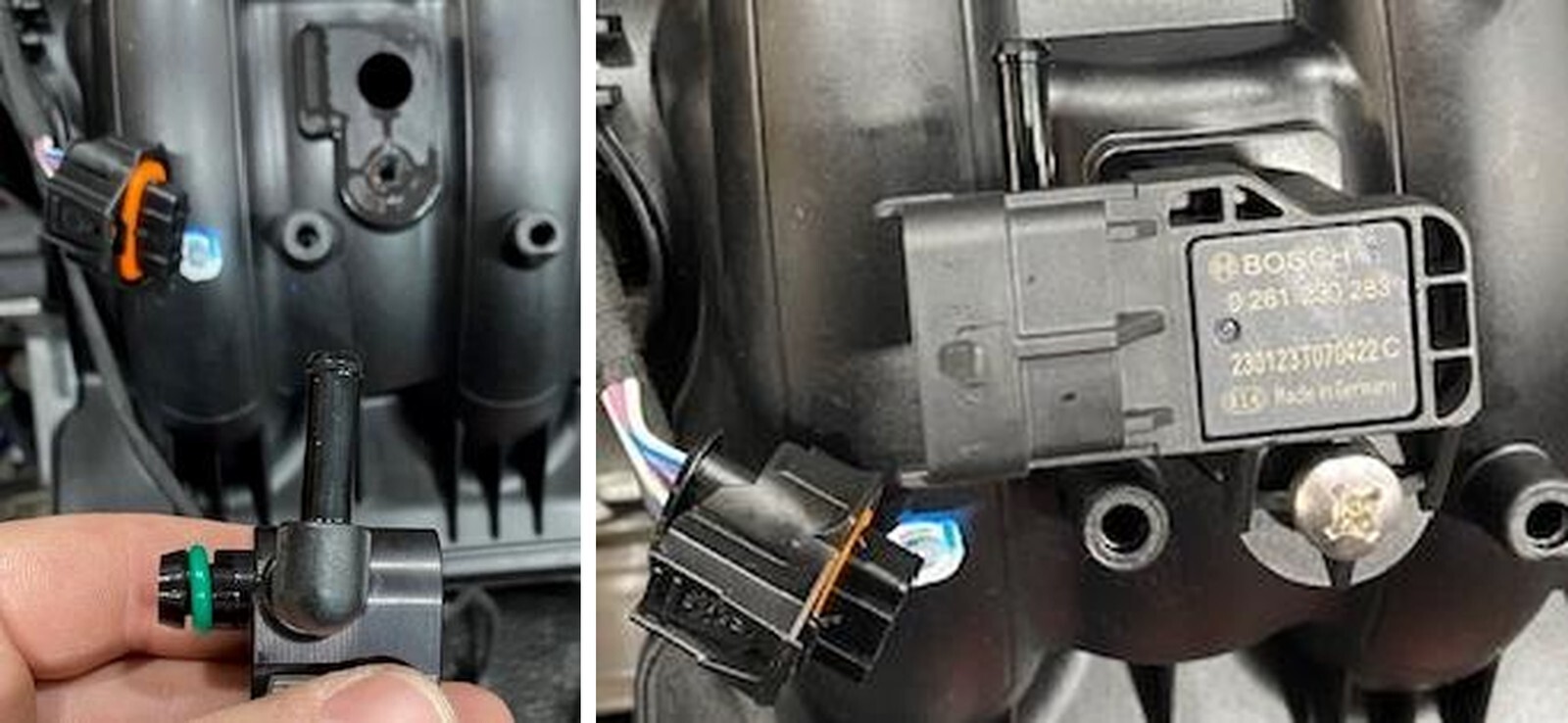
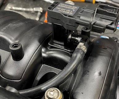
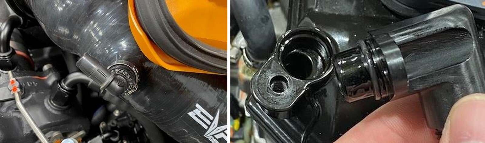
Remove map sensor connector. Don’t use a screwdriver. With a T30 remove the screw holding the MAP sensor in place.
77
Install MAP sensor shim with 90 Degree barb facing the fuel rail. Use dielectric grease on the O-Ring. Install supplied MAP sensor and fasten down with supplied screw. Reconnect the electrical plug, you may need to cut a zip tie.
78
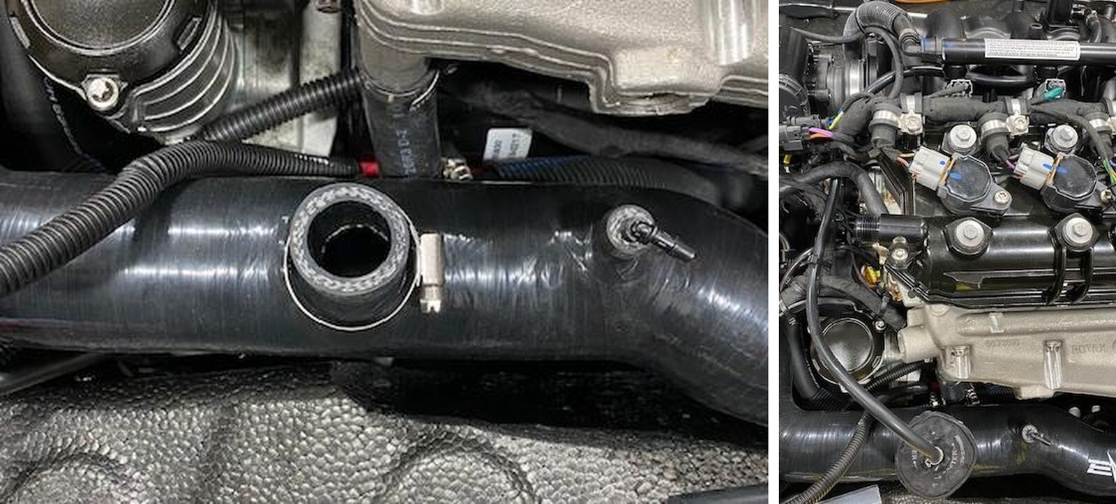
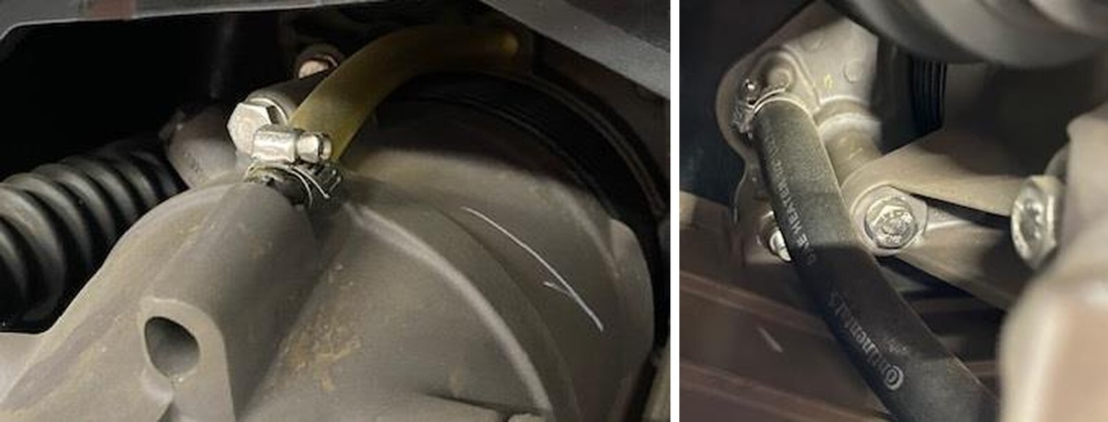
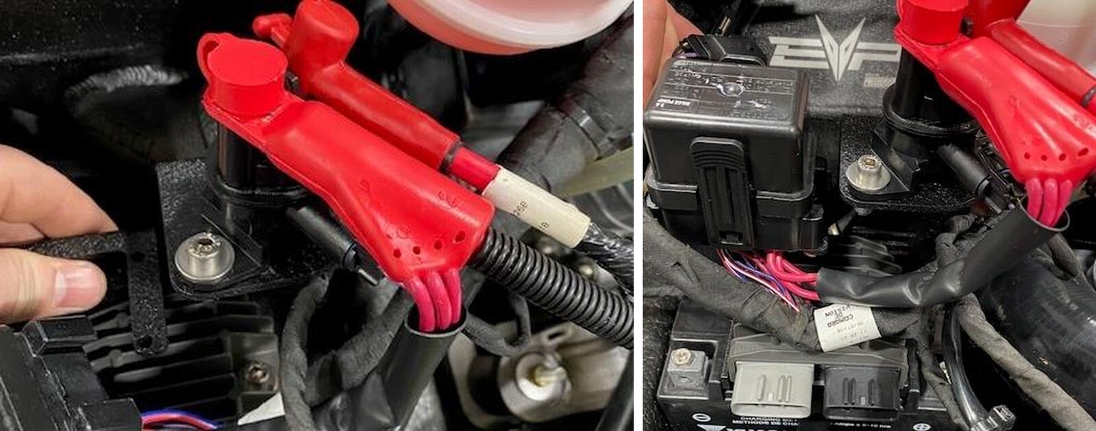
Install prefilter onto blow off valve. Install the BOV into the charge tube, fasten down with a 25-40mm worm drive. Install vacuum hose to BOV and fasten with 11.3mm pinch clamp.
79
Route the vacuum line as seen in the photo up to the MAP sensor shim. Loosely zip tie the vacuum line to hold it in place.
80
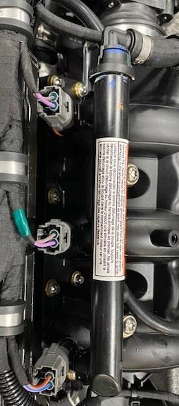
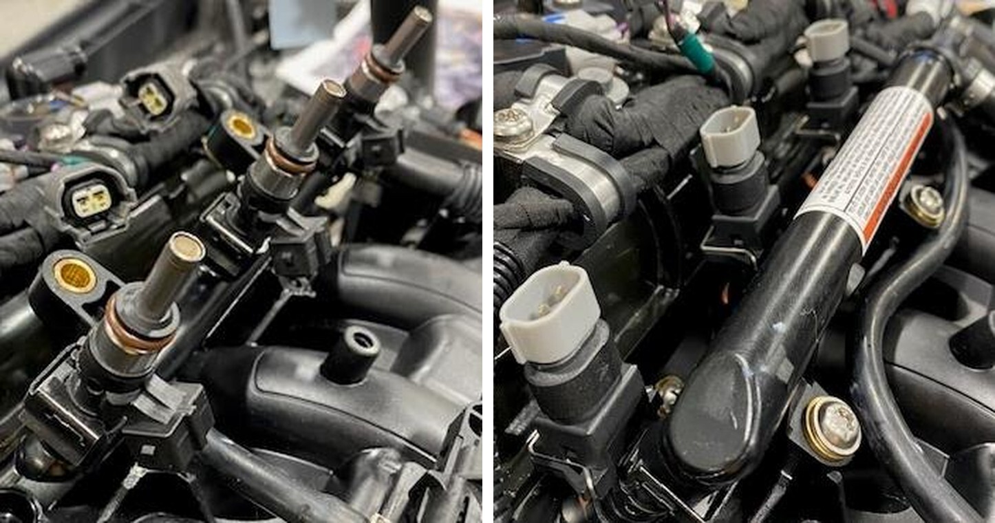
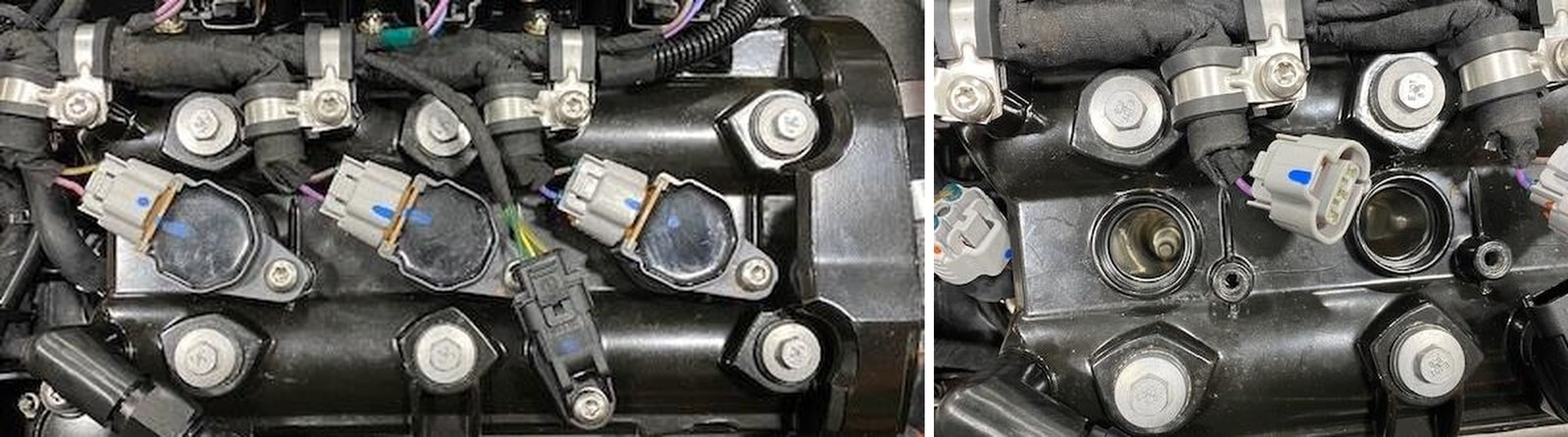
Unclip (3) injector connectors and remove the fuel rail screws using a T30.
81
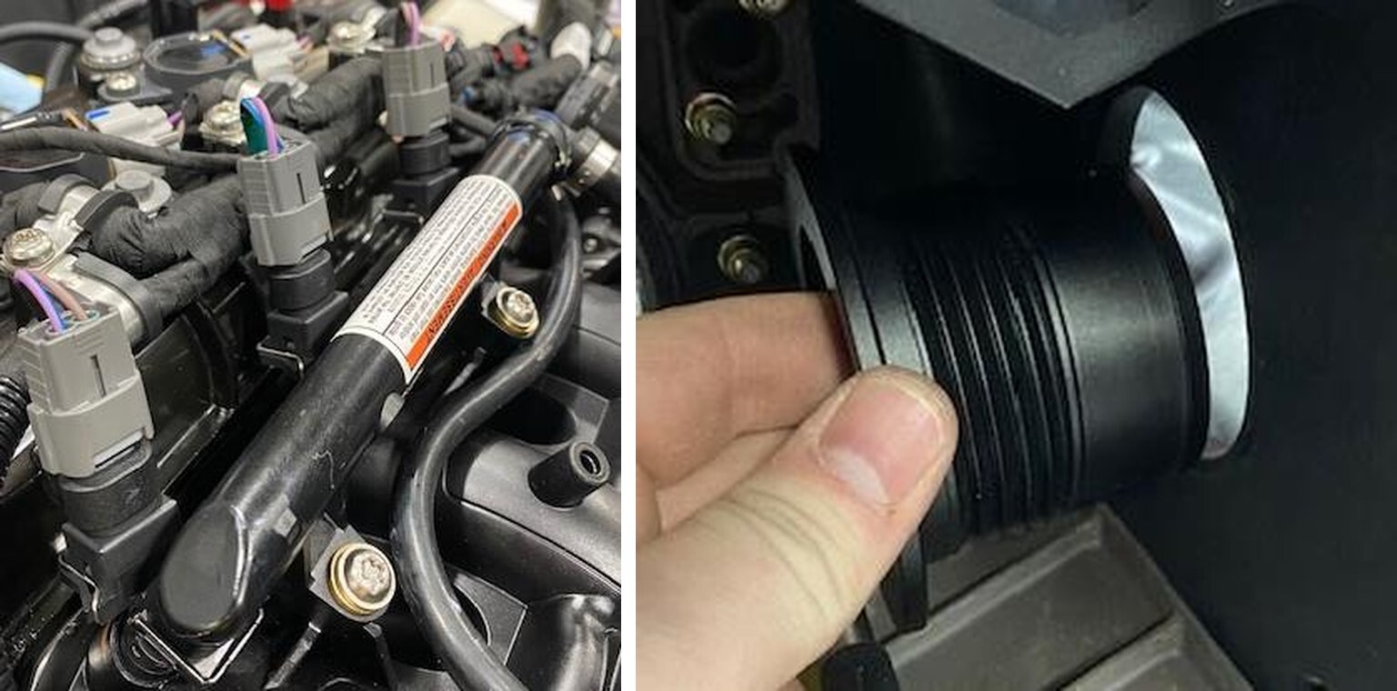
Flip the fuel rail up, remove the injector clips and remove the injectors. Install dielectric grease on the supplied injector O-ring and install. Reinstall the injector clips. Reinstall the fuel rail and hardware. Install (3) injector adaptors before reinstalling the injector electrical connectors.
82
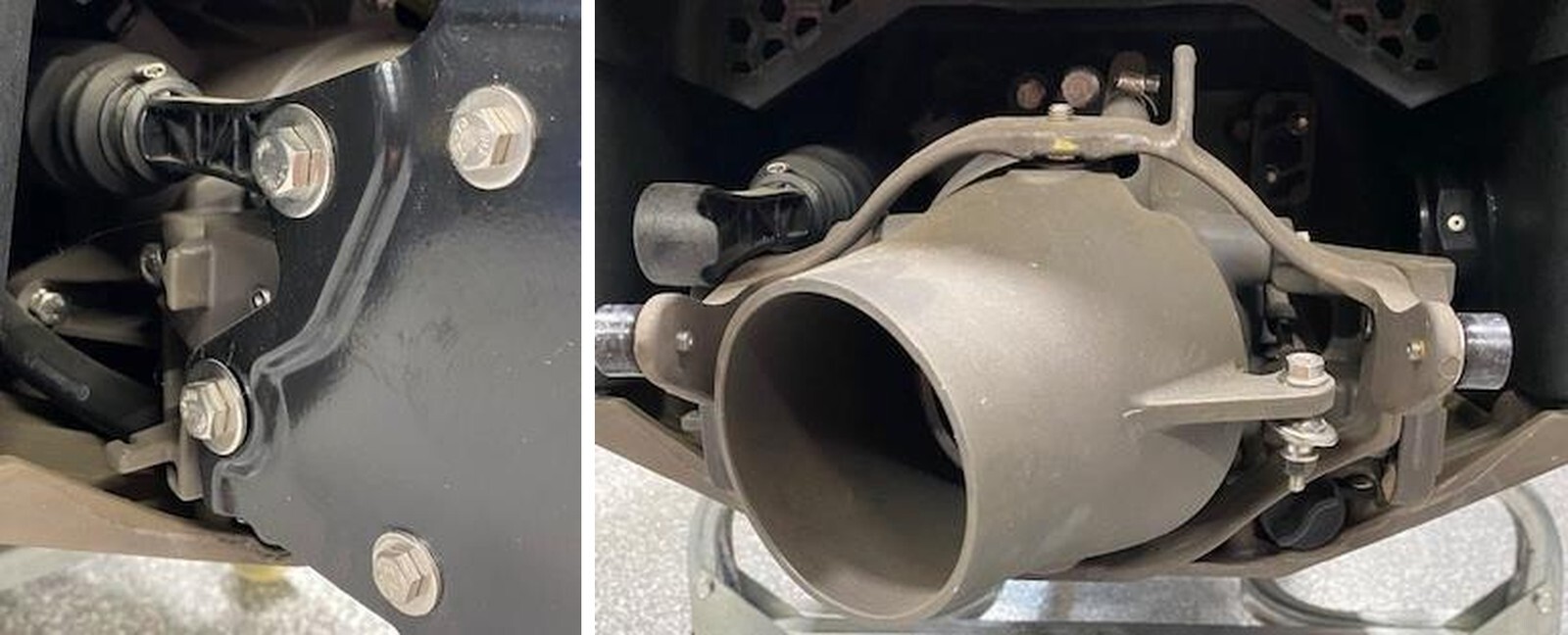
Install supplied O-ring onto exhaust outlet. Install the exhaust outlet from the outside of the hull into the inside. The threads should be on the inside of the hull. Install the OEM exhaust nut from the inside of the hull. Use supplied nut tool to snug up. DO NOT overtighten this plastic nut.
83
Install the rear exit silicone from the water box to exhaust outlet. Use (2) 312 T-bolt clamps to fasten silicone.
84
Install the 3.0” x 3.0” silicone coupler from the turbocharger to water box. Use (2) 359 T-bolt clamps to fasten down. Install the temperature sensor from the OEM water box, install anti seize on the threads and install into new water box. Use a 19mm wrench.
85
On the hull rear support, cut the zip tie holding the clear hose in place. Move this hose over to the other pillar and re zip tie. Install the air intake bracket to the rear support, fasten with M6 screw and locknut.
86
Install the air filter adaptor into the intake tube, half way. Use 32 constant tension worm drive on turbo side and (2) 110-120 worm drives holding the intake to the bracket and the air filter.
87
Install the 90-degree barb into the intake tube and fasten down with a pinch clamp.
88
Install the supplied valve cover fitting with O-ring. Use dielectric grease and fasten down with OEM T30 screw.
89
Install the straight 6AN push lock fitting onto the valve cover fitting. Install 1/2" silicone hose from the valve cover to air intake barb.
90
Remove the camshaft sensor connector and (3) coil connectors. It may help to loosen the P-clamps using a T30 socket. Remove the coil boots.
91
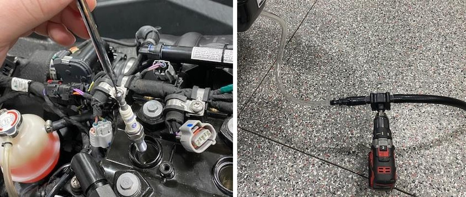
With a 5/8” spark plug socket loosen and remove the spark plugs. It is best to use a magnet to remove the plugs.
92
Install new plugs gapped at .018-.016”, using a magnet so you don’t drop the plugs. Reinstall the coil boots, screws, and connectors.
1
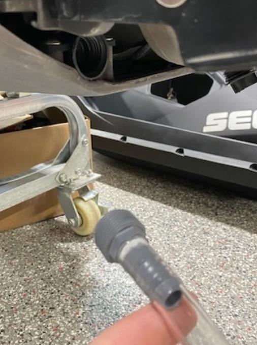
Get a gallon of antifreeze, pump, and a flush kit (if not already installed).
2
For these photos we installed a 3/4" threaded fitting to 1/2" barb attached to a drill pump.
3
Start the machine, let idle.
4
Start the drill pump, pushing antifreeze through the flush kit.
5
Once antifreeze starts coming out the jet pump, make sure its dark pink, stop pumping.
6
Let the machine run a few seconds longer, then shut off.
7
Remove the water box, dump out the fluids, pour a splash of antifreeze into the bottom and reinstall the water box.