Installation
1
Remove panel between the seats that allows access to the turbocharger.
2
Remove and label vacuum lines from the boost control solenoid going to the wastegate actuator, boost reference, and air box (corresponding colors). Boost solenoid located in the yellow box.
3
Remove the worm drive clamp holding the intake tube onto the turbo. (Shown in photo above).
4
Remove the worm drive clamp on the top of the air box.
5
Using a 13mm socket remove the 2 bolts behind the driver seat holding the air box to the firewall.
6
Remove the worm drive clamps or t-bolt clamps holding the charge tubes on. Intercooler to turbocharger and intercooler to throttle body. Remove from vehicle.
7
Using a 10mm socket, remove the (4) fasteners holding the intercooler in place. Be sure to unplug the intercooler fan. Remove intercooler assembly from vehicle.
8
Remove the nut on the V-band clamp holding the exhaust onto the turbo. You may need to use penetrating oil.
9
Remove the worm drive clamps holding the heat shielding on to the mid-pipe. Remove heat shields from mid-pipe.
10
Remove oil drain line from turbocharger by cutting the OEM clamp.
12
Remove oil supply line from top of the turbocharger.
14
Using a soft grip vise grip, pinch off the soft coolant lines that supply/return water to the turbo. About 2 inches from the hardlines.
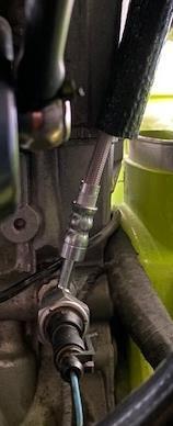
15
Cut the OEM clamps holding the soft coolant line to the hardline. Remove the soft coolant lines from the hard lines. The hardlines will come out with the turbocharger.
17
Remove bolts securing exhaust manifold heat shields – lower heat shield can be removed. Upper heat shield must stay on until the turbo is loose.
18
Using a 10mm socket or T40 Torx remove the fasteners holding the exhaust manifold to the engine and remove the turbo from the vehicle.
19
Remove oil pressure sensor and OEM oil line (be sure to save the copper washers).
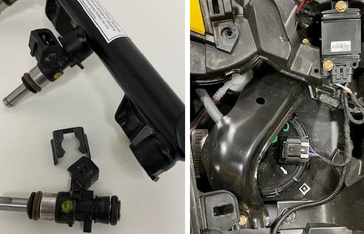
1
Slide the supplied oil feed line through the 5/8” supplied fire sleeve. Reinstall the OEM oil pressure sensor through the banjo side of the EVP oil feed line. Install the OEM copper washers on each side of the banjo fitting. See figure 1.
2
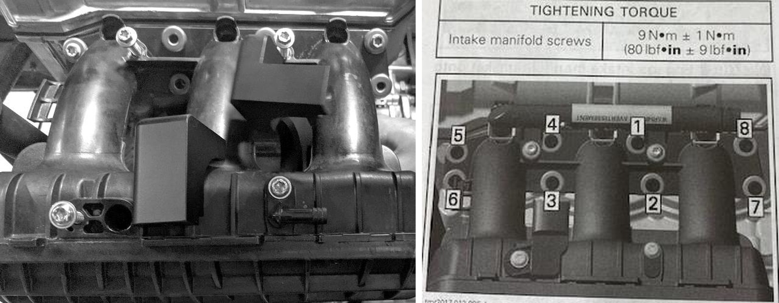
Install the M8 x 1.25 stud into the top hole of the center exhaust port. Thread the stud all the way in then back it out one full turn. Hang the OEM manifold exhaust gasket on the stud. See figure 2. . NOTE: If you have a P46/50 install the second stud on the top right hole.
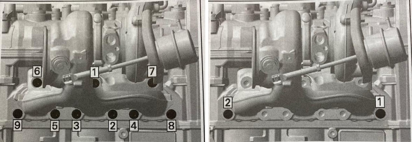
3
Install the new turbocharger reusing the OEM fasteners. Sequence 1: Torque the (2) retaining screws to 44 in-lb (4 ft-lb). Sequence 2: Torque the all (9) retaining screws to 17 ft-lbs. (23 Nm). Install the M8 x 1.25 copper flange nut onto the stud. Use a 4mm Allen wrench to hold the stud while torquing to 17 ft-lb. See figures 3-4.
4
Connect the EVP oil supply line to the top of the turbocharger. Remove the safety red cap before installing.
5
Connect the OEM rubber drain hose to the Paragon oil drain. Use the supplied 27mm pinch clamp to secure it.
6
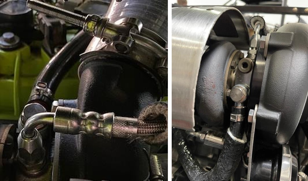
Install both 3/4" fire sleeves onto each 3/8” silicone water hoses. The shorter fire sleeve will connect to the rear of the turbocharger coolant fitting and run to the “T” underneath the coolant resivor. Use (2) 18mm pinch clamps. The longer fire sleeve with silicone hose will connect the the front barb coolant fitting and connect back to the OEM soft coolant line using the supplied 3/8” hose barb. Use (3) 18mm pinch clamps.
7
Install the 3/4-3/4 barb into the V-Flow and secure with a pinch clamp. NOTE: If using a catch can, cap the hose barb with supplied cap. Install the V-Flow to the turbocharger and air box. Reinstall the (2) 13mm bolts securing the airbox to the firewall. Tighten the V-Flow down.
8
Reinstall the (3) vacuum lines coming off the boost control solenoid. Use the (2) 3/16” 90-degree hose barbs and (2) 7inch vacuum hoses to connect the wastegate and boost reference port. Reuse the OEM airbox vacuum line and clamp and connect to the V- Flow.
1
Remove (1) factory head bolt and replace with (1) ARP 2000 Head Stud 9mm. Apply supplied assembly lube to the top of the stud threads and both sides of the washer and nut. Install washer first, then thread nut onto the top of the stud - torque nut to 45 ft lbs. Be very careful not to drop anything into the engine! NOTE: Do this process one at a time for all remaining head bolts. Never loosen more than (1) head bolt without replacing and torquing with a stud. This will ensure the cylinder head gasket does not lose its seal. Once all factory bolts have been replaced with studs, torque the head according to the “REPLACEMENT” pattern and torque steps below. When all studs have been torqued to the final value, re-torque to the final value (3) more times.
1
You don’t need to remove the OEM plenum from the vehicle. Unplug the MAP sensor and remove from the plenum. Cover the MAP sensor hole.
2
Using a Dremel tool or air grinder, remove tabs shown in the picture below. Be careful not to compromise the integrity of the runners by only removing as much material as necessary for the clamp.
3
Once tabs are removed put the left half of the inside in place first and then the right.
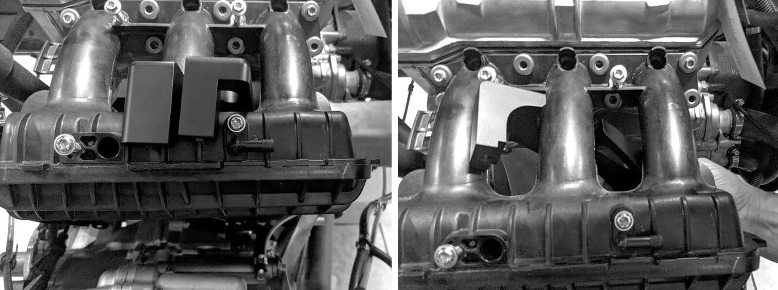
4
Now that all (3) pieces are installed, start all (4) bolts before tightening them down. Put Loctite on the threads of the bolts.
5
When tightening the (2) bottom bolts it is easiest to use a 6mm Allen socket.
6
Tighten all (4) bolts.
1
Install the (2) supplied MAP sensors. One is located on the throttle body; one is located on the intake plenum. The MAP sensor on the throttle body will use supplied MAP sensor harness. NOTE: Use dielectric grease on the green O-rings for installation. If you are getting MAP sensor codes, 180 the plug. NOTE: Tighten both OEM throttle body clamps or it will pop off when boost is built.
1
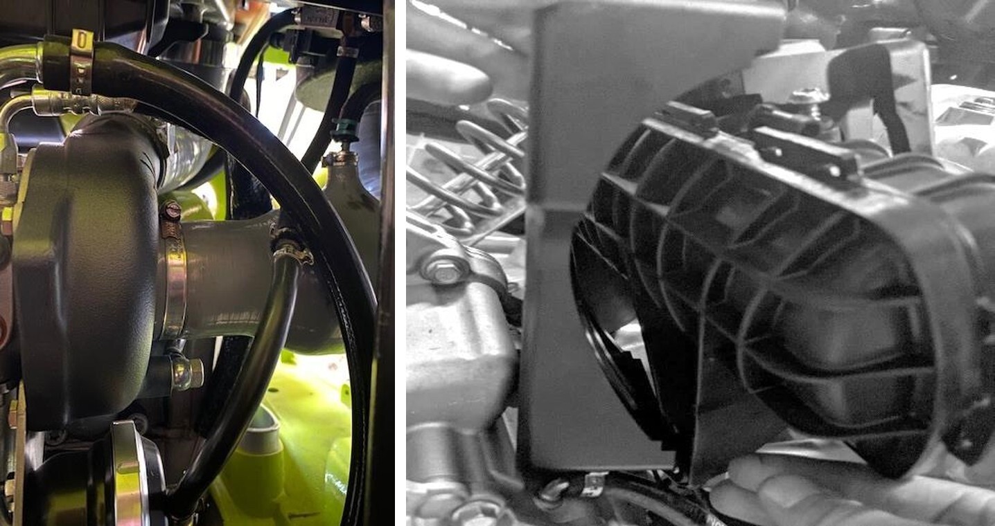
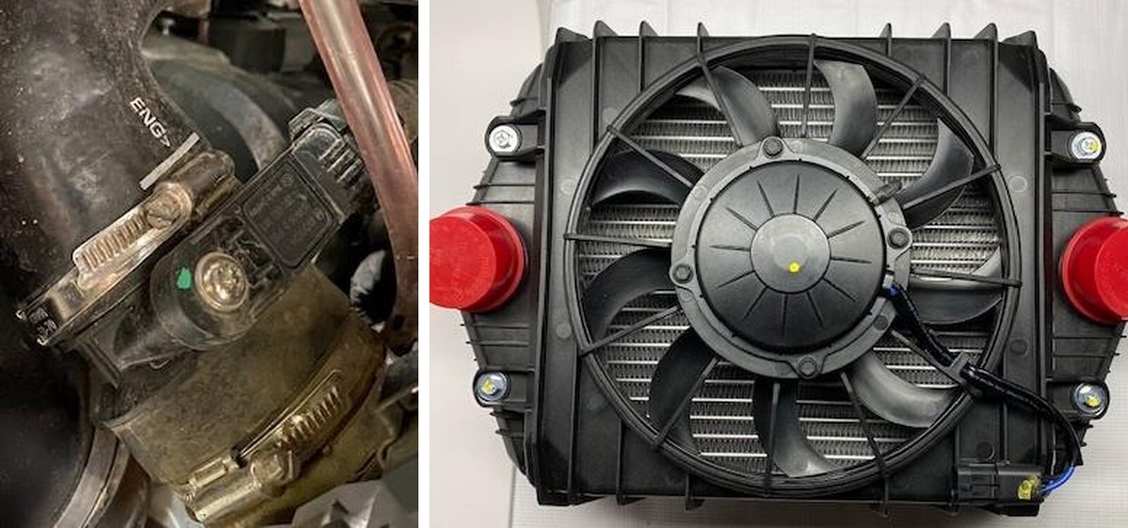
Remove plastic shroud off the OEM intercooler and air box.
2
Unplug the electrical plug from the intercooler fan and the vehicle.
3
With an 11mm socket loosen both clamps on the charge tubes. Remove from intercooler.
4
With a 10mm socket, loosen (2) bolts on the back side of the intercooler.
5
Pop the access panel out of the firewall from the inside of the car.
6
With a 10mm socket, loosen (2) bolts on the front side of the intercooler. NOTE: may need a shallow socket for the bolt behind the passenger seat.
7
With a screwdriver, remove the OEM fan off the OEM intercooler. (Figure 1).
8
Flip the OEM intercooler fan upside down, there will be small modifications needed.
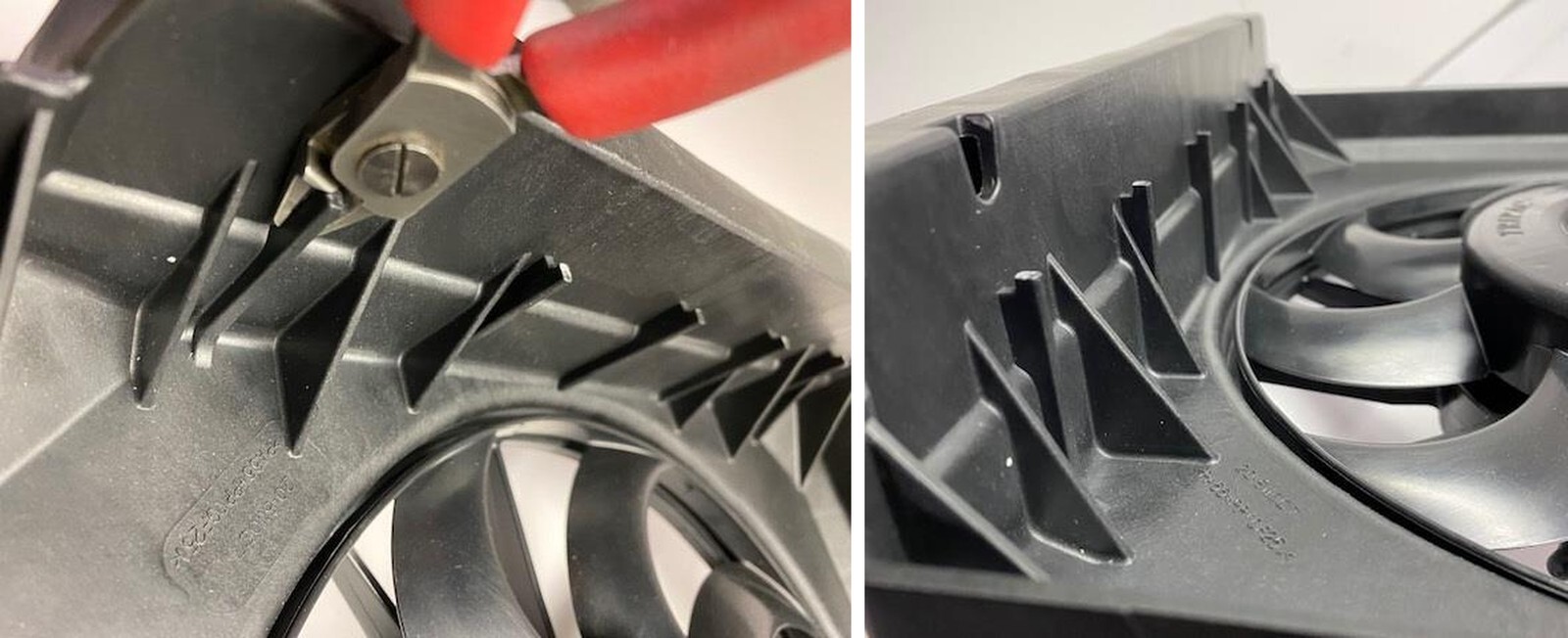
9
With a sharp side cutter or Dremel tool, the tabs on the OEM intercooler need to be taken off to fit on the EVP intercooler. (See figure 2-3).
10
Mount the OEM intercooler fan onto the EVP intercooler. Tighten down (4) Philips screws with a screwdriver.
11
Install the intercooler and connect the charge tubes to the new intercooler. Tighten down charge tube clamps with a 11mm socket.
12
Replace (4) bolts holding the intercooler into place, use a 10mm socket.
13
Reconnect the plug from the fan to vehicle connection. Figure 23.
14
Reconnect air intake and intercooler shroud to the vehicle.
1
Remove all (3) spark plug coil connectors. Remove all (3) retaining screws and ground connectors. Pull the ignition coils out of the block. Now the spark plugs can be accessed and changed out with supplied EVP plugs. Torque the new spark plugs to 97 in-lb (11 Nm). Reinstall the coils, ground connectors and retaining screws.
1
Install the lower charge tube onto the throttle body up to the intercooler.
2
Install the Blow Off Valve into the charge tube. Run the vacuum line from the BOV to the plenum. Port shown up in plenum photo.
3
Install the smaller charge tube from the intercooler to turbocharger. Use supplied clamps.
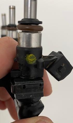
1
With brake cleaner, spray around all (3) injector ports and fuel rail. Wipe debris away with a rag. Turbo and Turbo R models press the metal clip down and remove the connector from the injector. Remove the fuel hose from the fuel rail. Push the connector in and spread left/right side away from the fuel rail. Remove the fuel rail, keep the O- rings with the fuel hose. Remove the (2) fuel rail screws.
2
Remove the injector clip, once the clip is removed you can pull the injector out of the fuel rail. Install the EVP injectors, use dielectric grease on the O-rings allowing for easier installation. Place the injector clip back onto the fuel rail, make sure the clip is in both grooves. Reinstall the fuel rail in reverse order. Install the supplied injector clips onto the injector. Plug the harness connector into the adaptor.
1
Reinstall your free-flowing exhaust or if you have purchased on of our EVP handcrafted exhaust kits please find those installation instructions on our website.
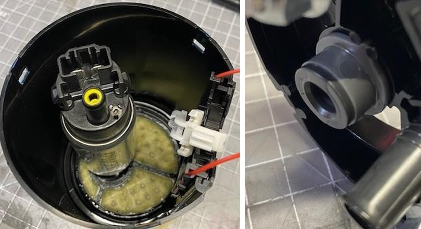
1
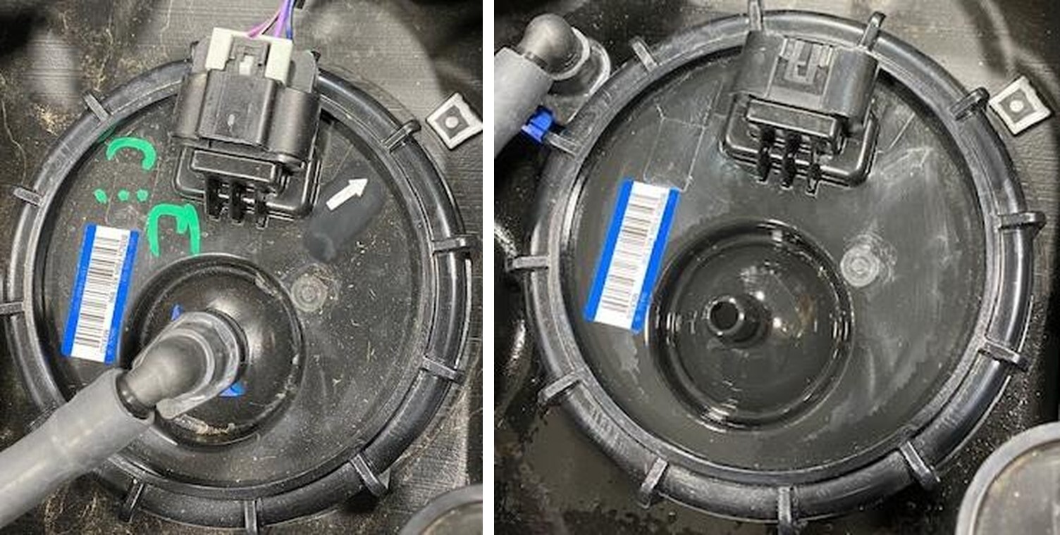
Remove the fuel pump safety bracket by removing (2) 10mm screws. NOTE: Notice the arrow on the fuel pump is facing the middle of the box. When reinstalling make sure the arrow is facing the middle of the box or your fuel float will read incorrectly.
2
Remove the silver safety clip on the electrical connector, then remove plug. Remove the blue safety clip on the fuel connector, press the black quick connect and remove the fuel hose.
3
Remove the fuel pump nut, be careful not to damage it. The fuel pump assembly has springs so the hat might spring up about one inch. NOTE: If you are changing fuel octane, drain your fuel tank now!
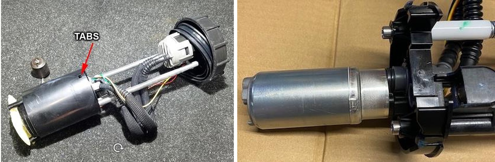
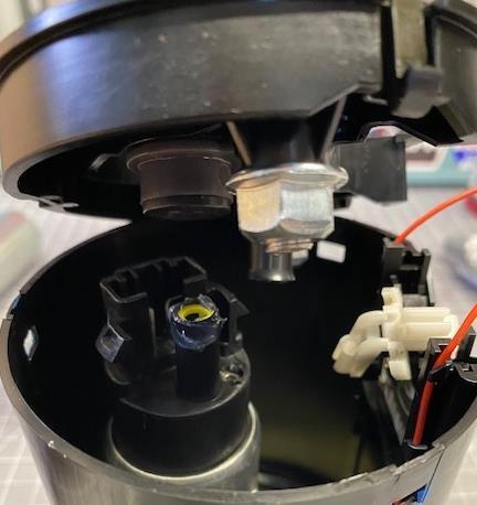
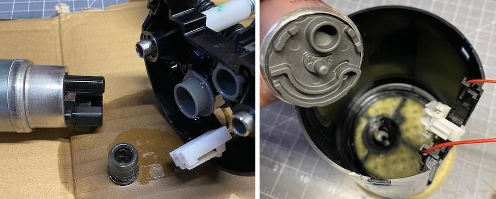
4
With the fuel pump on a workbench and all the fuel drained out of the pump assembly, press in on the (3) tabs to release the housing covering the tank.
5
Slide the top hat away from the surge tank. The fuel pump may come with the hat or stay in the surge tank. Remove the fuel pump and rubber gromet from the lid.
6
Install the new pump into the bottom surge tank. Make sure both tabs are locked into place. The pump shouldn’t move when properly locked into place.
7
Apply dielectric grease to the rubber gromet. Reinstall it into the upper lid inlet port. Apply dielectric grease to the fuel pump outlet port. Slowly reinstall the upper lid to the surge tank, making sure all (3) clips meet and fuel pump and inlet meet. Watch the float wires.
8
Reinstall pump assembly.
9
Replace OEM fuel pump fuse with the supplied 20-amp fuse in location F5.