Installation
1
Both XP and ADV models will be required to remove the bed off the vehicle, those instructions are in the service manual. These instructions start after many have been removed.
2
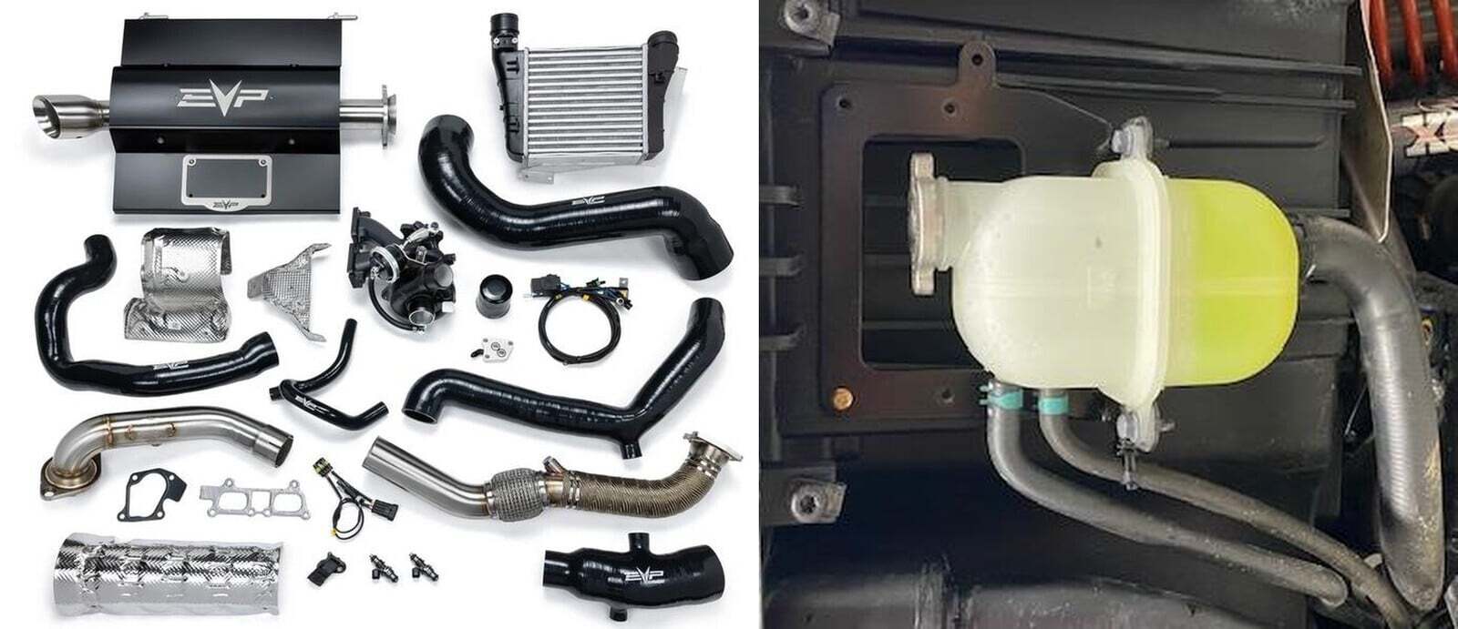
Remove the (4) 8mm screws holding the coolant reservoir bracket to the bed.
3
Remove (2) rear bed mounts, use a 16mm socket and wrench. Unplug the bed connector located rear driver side frame.
4
Remove Figure 2 the rear seat to bed bolts, 13mm bolt and nut.
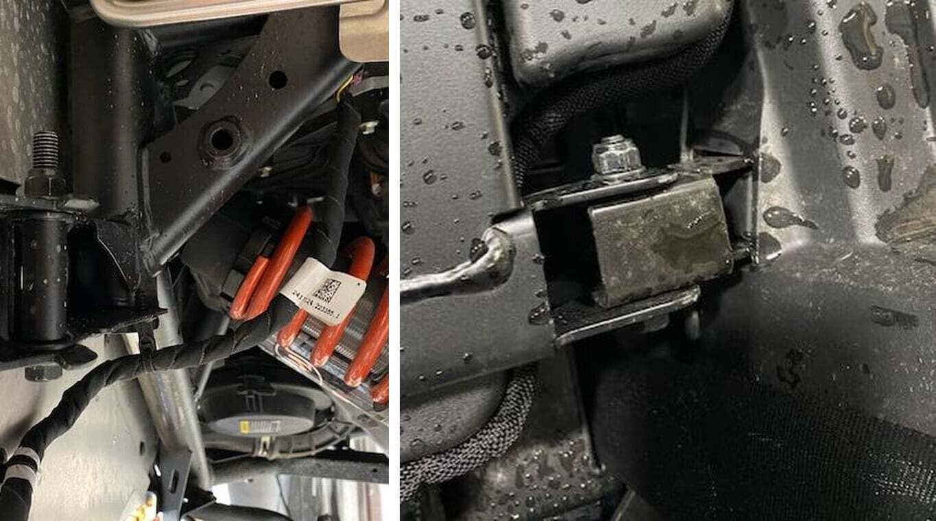
5
Remove both driver and passenger side back seat mounts. Remove (2) 13mm screws and (1) T-40 for the strap.
6
Remove the bed from the vehicle.
7
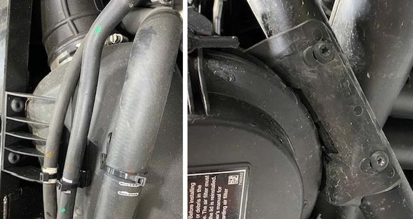
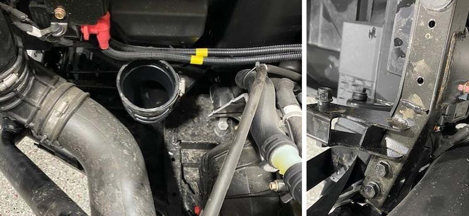
Remove the airbox, unclip (3) coolant lines and remove (2) T-40 screws from the top and (2) T-40 screws from the bottom frame rail.
8
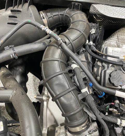
Remove the airbox to throttle body tube, loosen (2) worm drive clamps and (1) push dart. Remove the coolant line from the rubber grommet.
9
Remove the crankcase vent from the intake tube, loosen self-tighten clamp.
10
Loosen the fresh air intake tube from the airbox and remove.
11
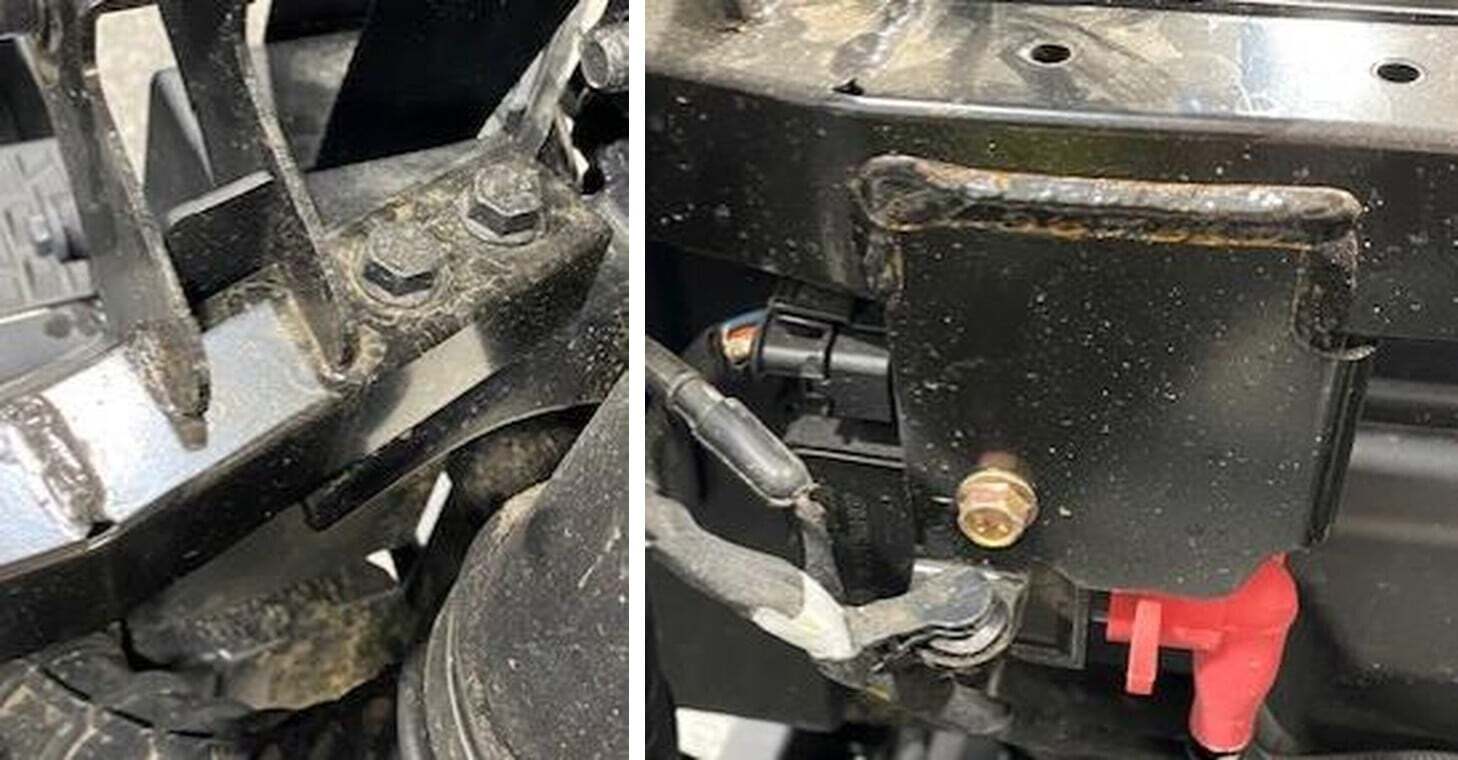
Remove the upper seat bracket, (2) 13mm bolts and nuts on each side.
12
Remove the 10mm bolt holding the coil pack to the upper seat bracket.
13
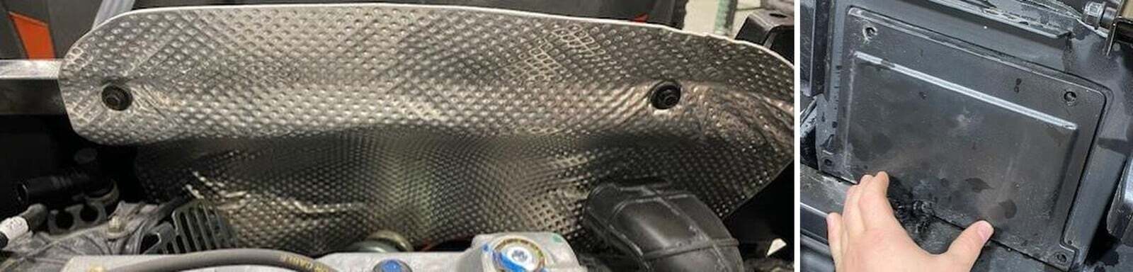
Remove the (2) 10mm bolts on the heat shield.
14
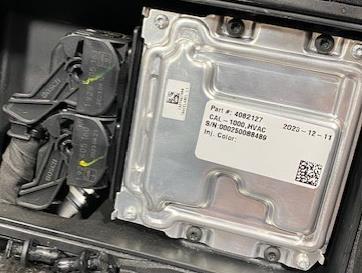
Remove (4) push darts holding the ECU cover on. Remove (4) T-25 holding the ECU in.
15
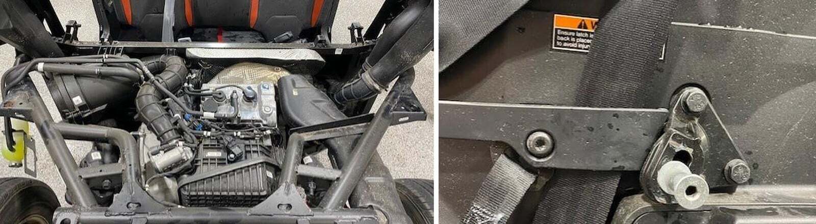
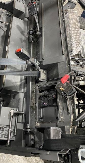
Remove the lower seat belt mount, (4) 16mm screws. Remove (5) T-40 screws.
16
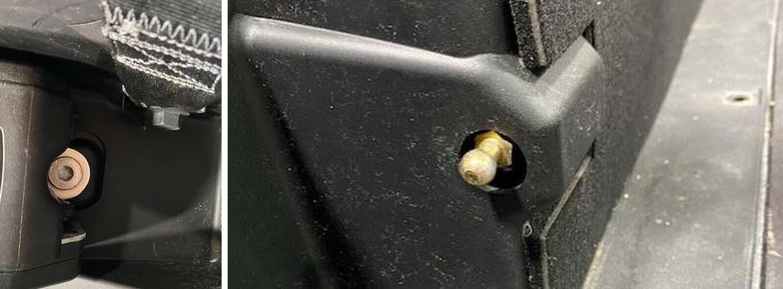
Remove both seat belt retractors, 16mm nut on the back side of firewall. Remove the lower seat belt mount 15mm bolt and nut.
17
Remove the lower seat shocks, remove the shock mounts with a 12mm socket.
18
When removing the lower firewall panel, slide the ECU connectors through the open hole in the ECU box.
19
Loosen the flange bolts with springs using a 13mm socket, slide the OEM muffler out of (3) rubber isolators. Slide towards the driver’s side of vehicle.
20
Remove the large black heat shield, remove (4) 10mm screws.
21
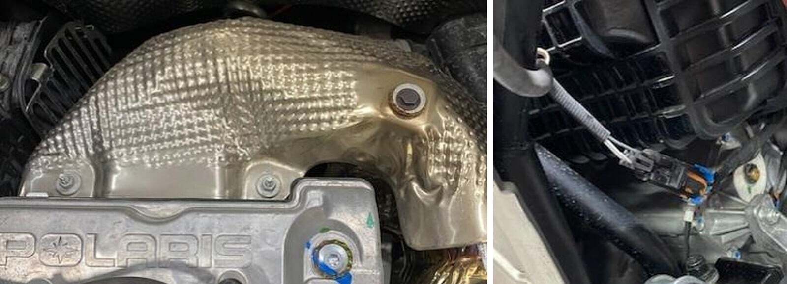
Remove the header upper heat shield, (1) 10mm screw and (2) 10mm nuts.
22
Unplug the 02 sensor from the harness. Loosen the 02 sensor with a 22mm wrench.
23
Remove (6) 6mm Allen screws holding the head pipe to the head.
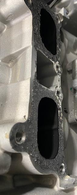
24
Remove the head gasket and clean the surface.
25
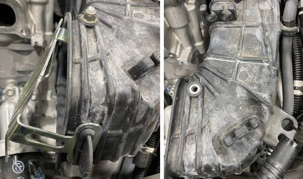
Remove the debris guard off the CVT boot, (1) 10mm nut and rubber gromet.
26
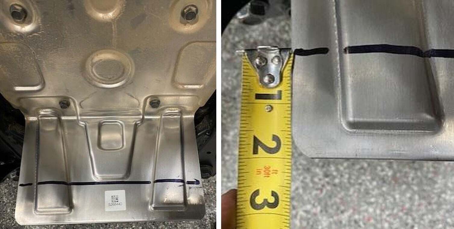
Cut (4) ribs back on the red line. Be careful not to pinch any lines.
27
Install the new CVT guard as shown. Use a 5/16” drill bit and measure out the hole locations. Install with supplied oversized washer and M6 x 1.0 flange screw.
28
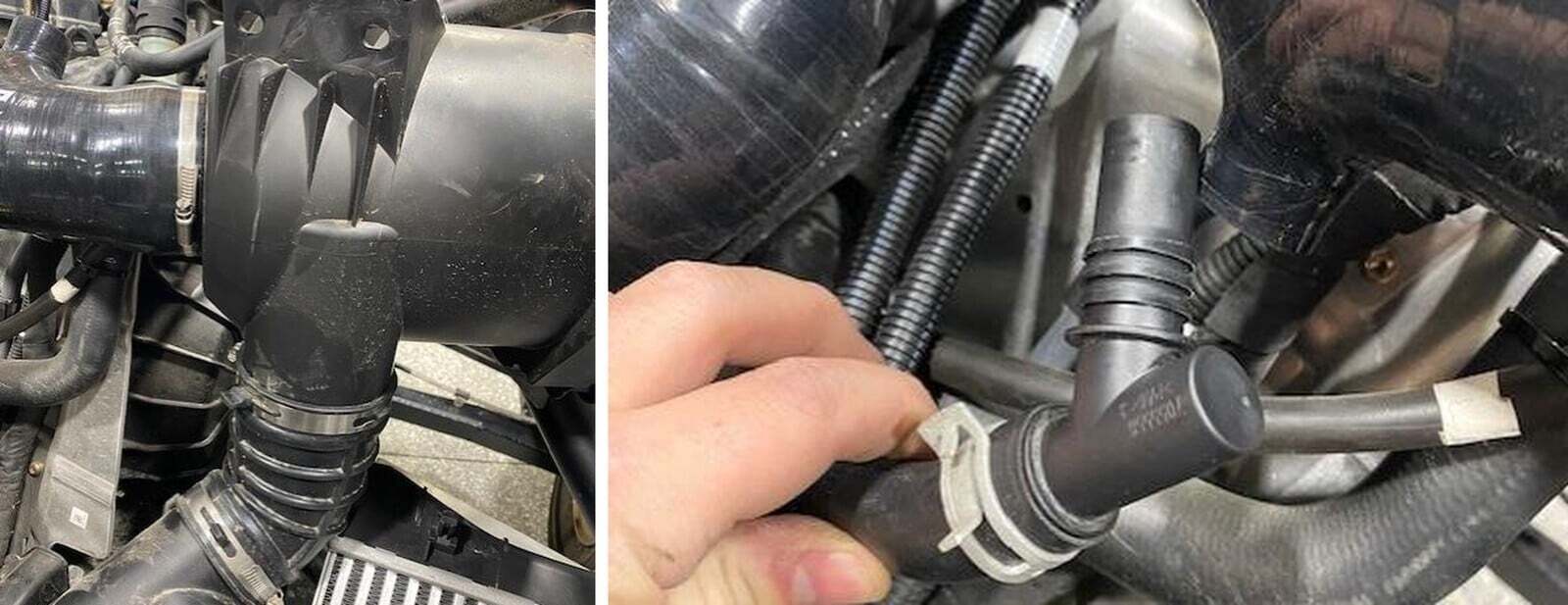
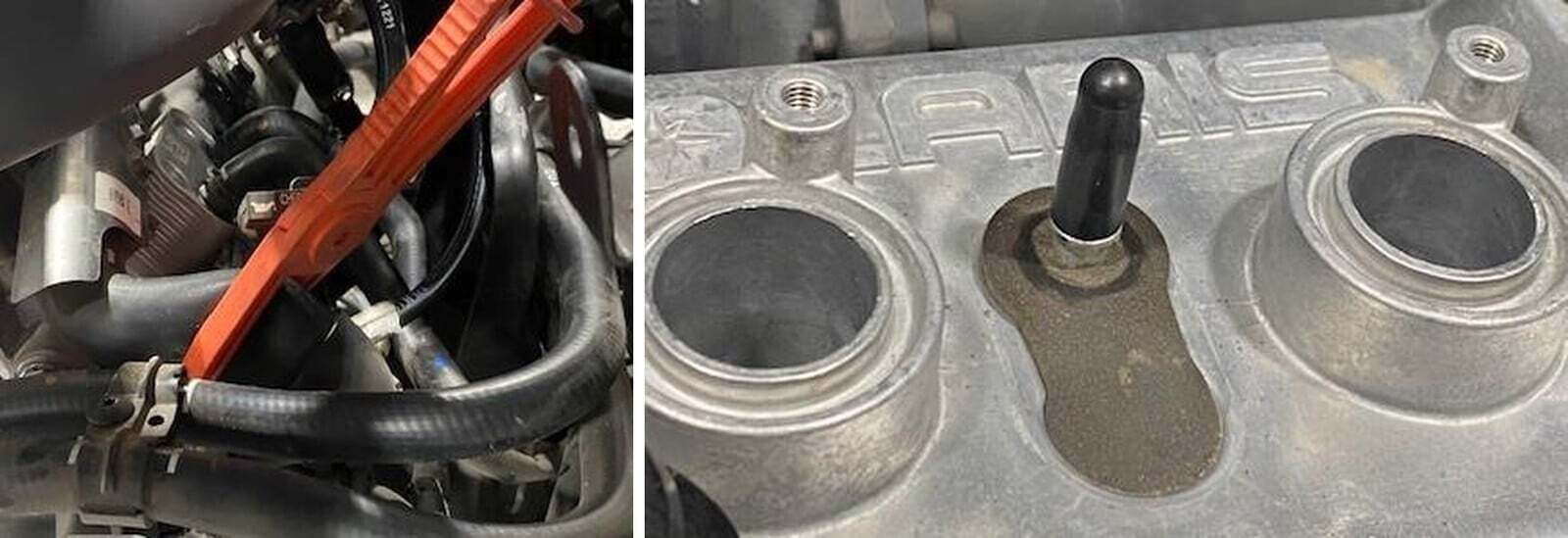
Pinch off all coolant lines going to the engine and valve cover. Remove the coolant reservoir cap if you haven’t done that already. Once all coolant lines are pinched off remove the valve cover coolant line. NOTE: there may be pressure behind this hose, cap the barb off with a silicone cap.
29
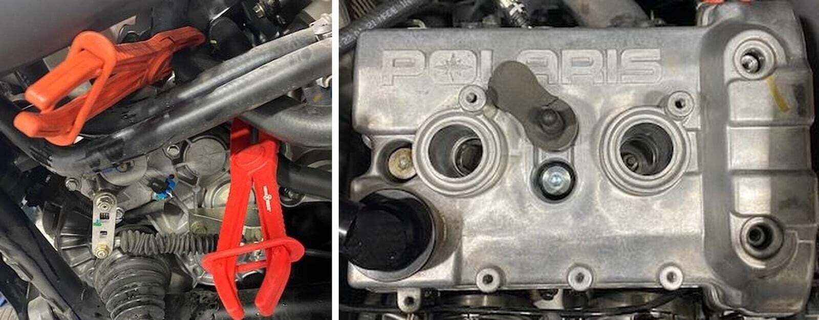
Disconnect the spark plug coil packs and loosen the coil packs with a 8mm socket. Pull the coil packs out of the valve cover.
30
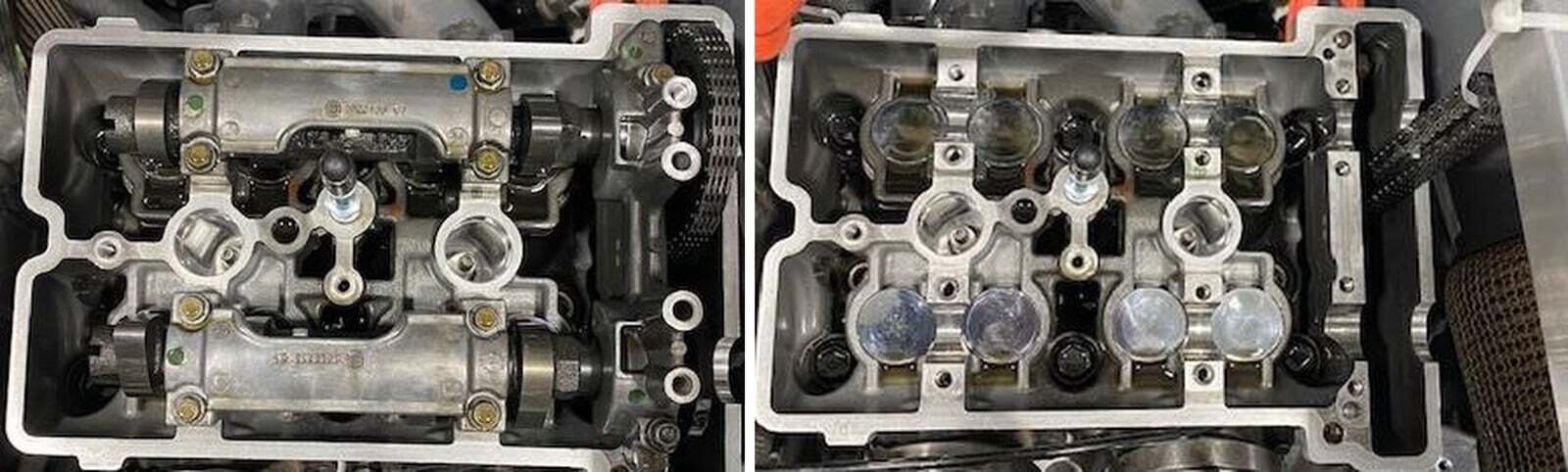
Remove the (4) valve cover screws using a T-40 torxs. Keep the rubber gromets. Remove the valve cover and gasket.
31
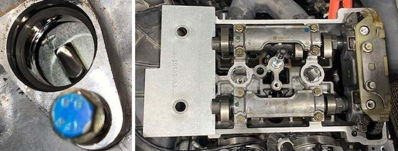
Remove the crankcase position sensor using an 8mm socket. Find TDC and slide the cam locking tool into place. Tool Number: PU-50563-1. To double check TDC you can find a (+) sign looking through the crankcase position sensor port. NOTE: some xpeditions don’t have a “+” symbol, some are just a deep cut.
32
Remove the cam chain tensioner using a M6 Allen. Check gasket for any tears.
33
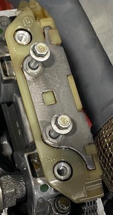
Remove the (2) retaining bolts holding the top guide in place, using a 8mm socket.
34
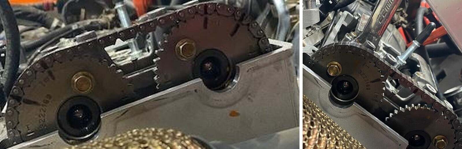
Clean the cam sprockets and chain. With a sharpie make (2) marks on each gear and chain for installation purposes.
35
Place a 22mm wrench on the intake cam, spin the clutch to release pressure off the valves while loosening the intake cam sprocket. Remove the sprocket once hardware is removed.
36
Loosen both camshaft carriers using a 8mm socket. Remove carriers and cam shafts from the engine. Zip tie the cam chain up to the bed mount so the chain doesn’t come off the crank.
37
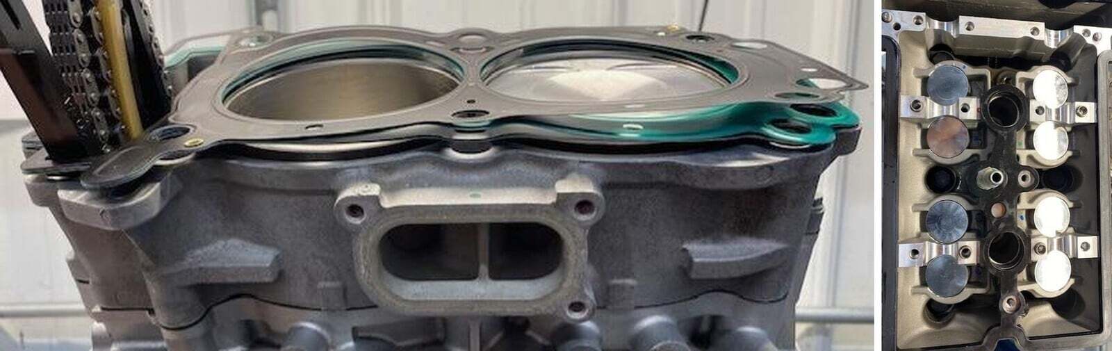
Remove (6) head bolts with washers and discard. Remove the head. Remove the head gasket and clean up the head gasket surfaces, removing all debris. Install the new multi-layer head gasket.
38
Reinstall the head. Apply a small amount of assembly lube onto the threads of new head bolts with washers. Hand tighten all (6) head bolts. See the torque sequence on next page.
39
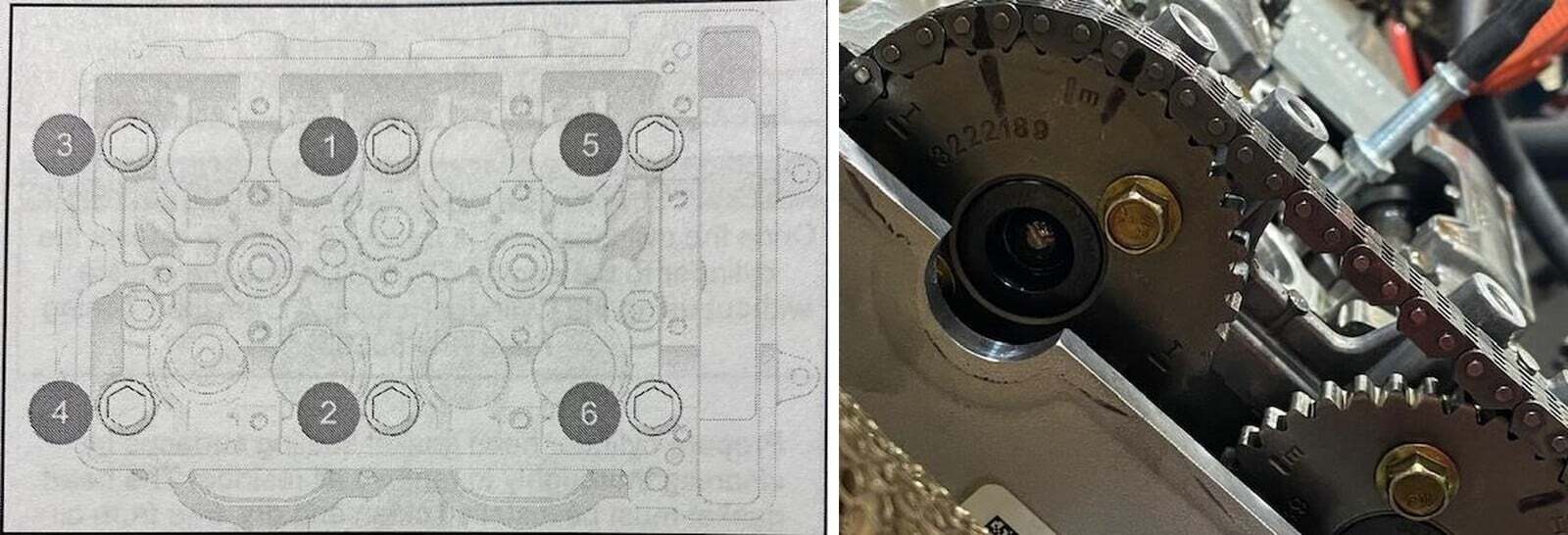
See torque sequence and specifications below.
1
13 ft/lb.
2
26 ft/lb.
3
180 Degrees.
4
Final 180 Degrees.
1
88 in/lb.
40
Reinstall the camshafts and camshaft carriers. Snug up the camshaft carriers. Install cam shaft timing plate back into the camshafts. Verify TDC mark on the flywheel making sure the engine is still timed. Install the intake sprocket back onto the intake camshaft. Make sure your sharpie marks align properly. Apply red Loctite to the sprocket hardware and torque camshaft sprocket to 14 ft/lb. Reinstall the outer camshaft carrier and chain guide. Torque all camshaft carrier bolts to 7 ft/lb.
41
Remove the spring retainer bolt out of the spring tensioner and push the adjuster all the way in. Install the cam chain tensioner into the block and torque the mounting bolts to 7 ft/lb. Install the tensioner spring, washer and retainer bolt. Torque spring tensioner bolt to 12 ft/lb.
42
Rotate the crankshaft two full revolutions to verify camshaft timing.
43
Reinstall the valve cover gasket, place a silicone based liquid gasket around the two lobes before installing. Place the valve cover over the camshafts and torque (4) valve cover screws to 7 ft/lb.
44
Remove the spark plugs and install supplied EVP spark plugs. EVP gapped plugs are .018-.020”. Torque plugs to 9 ft/lb.
45
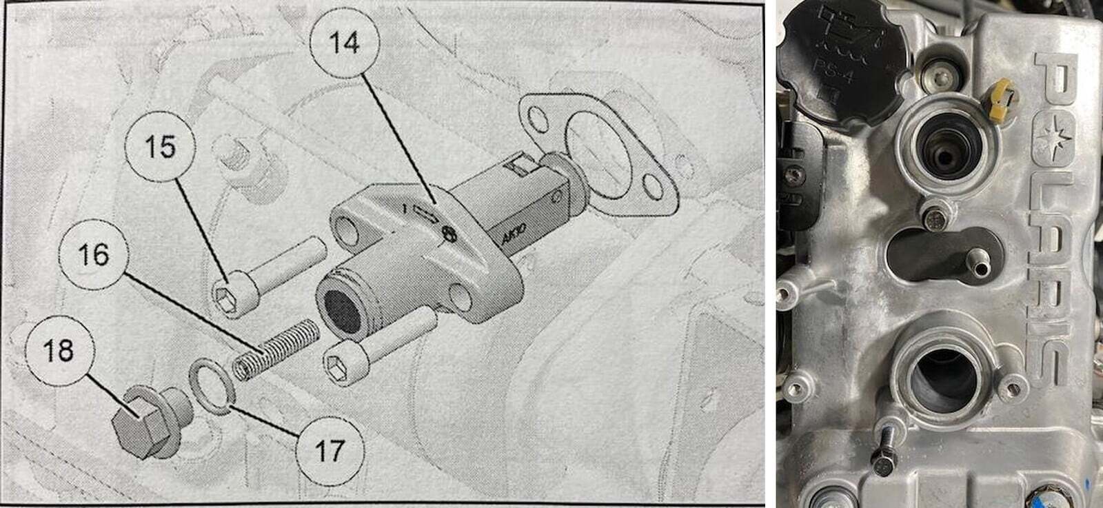
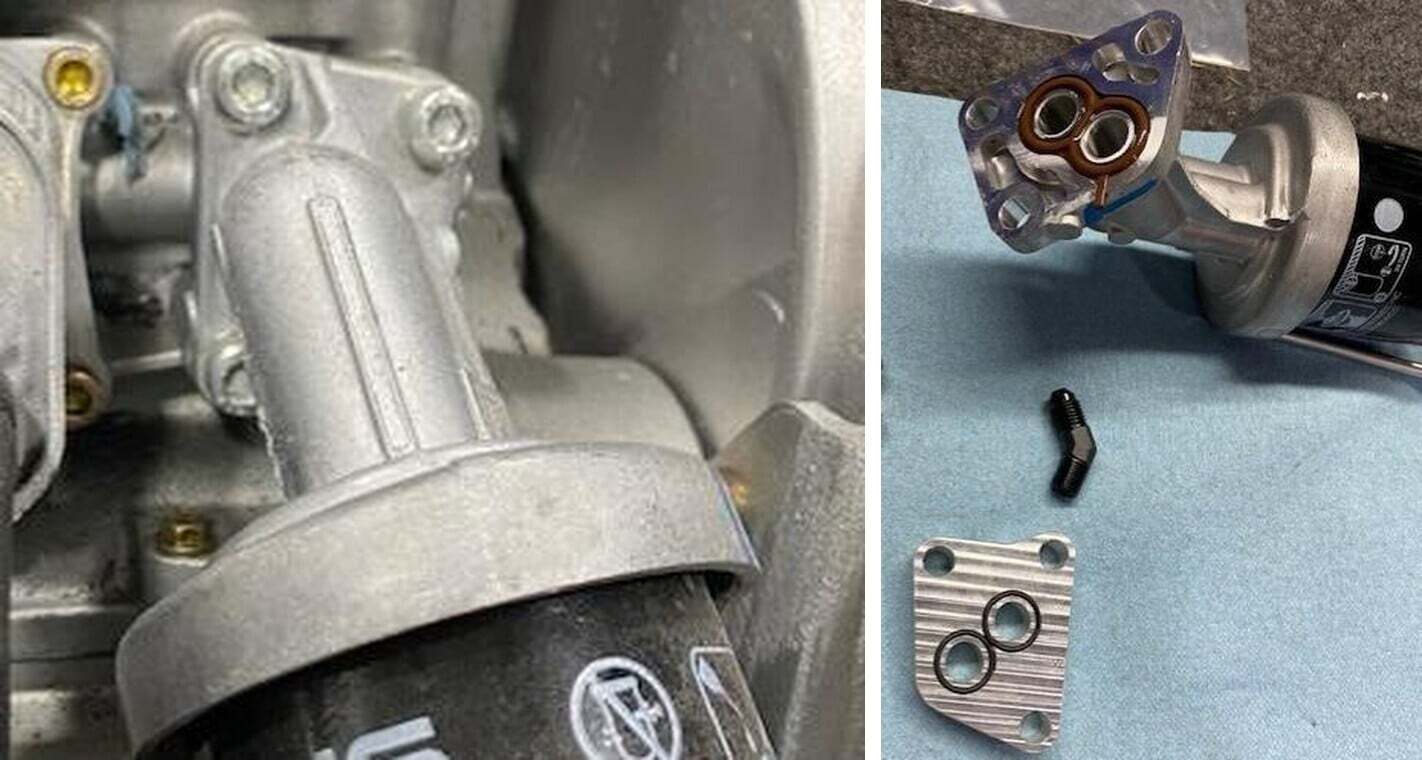
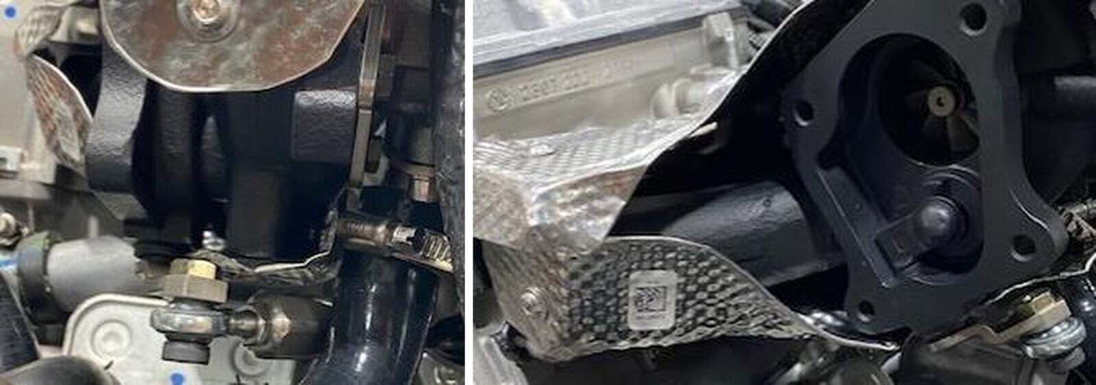
Remove the (3) 6mm Allen screws holding the oil filter housing onto the block.
46
Install the (2) O-rings into the billet oil filter adaptor. Install the NPT fitting with Teflon into the top of the billet block at a 90 degree angle.
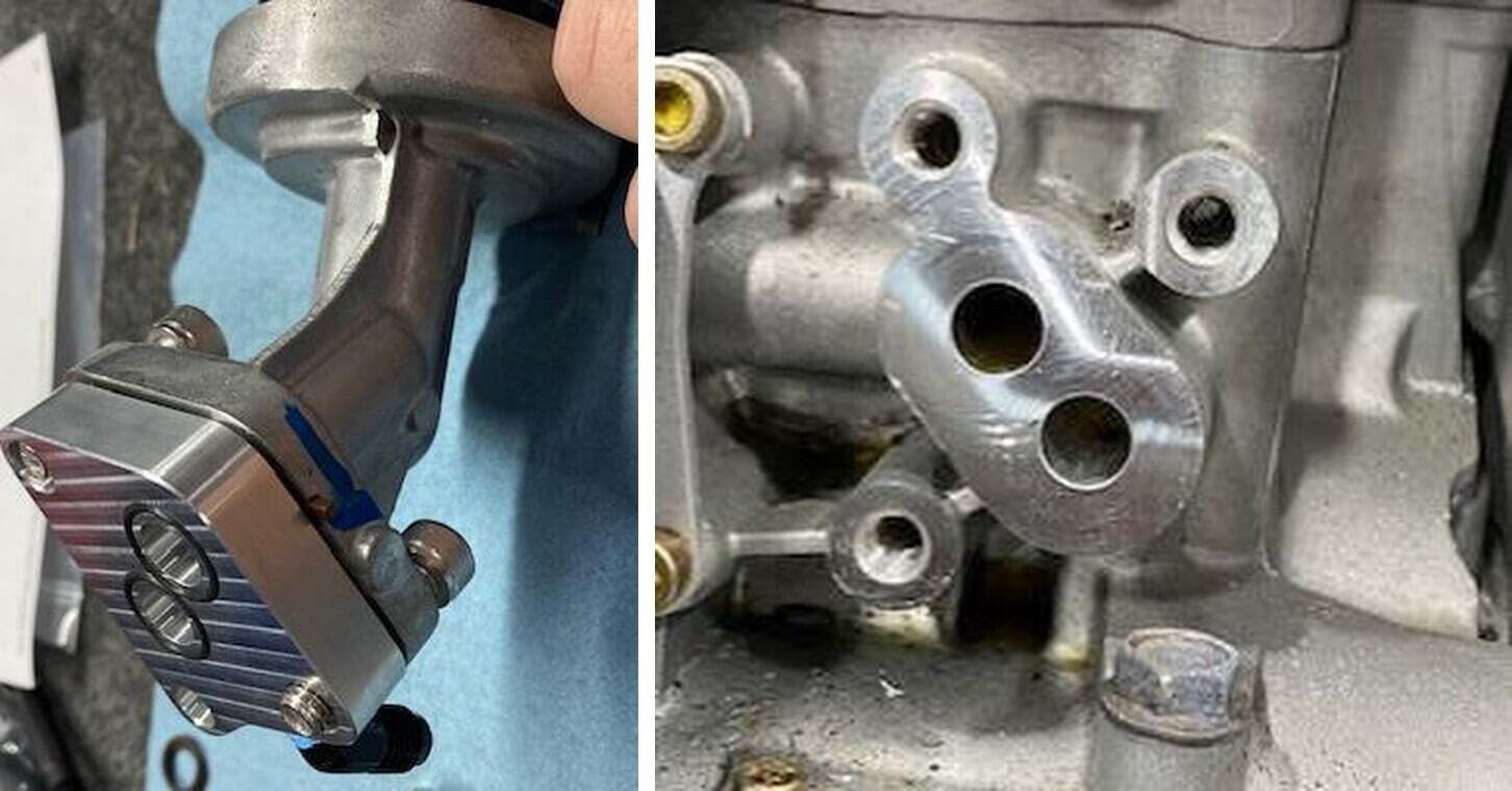
47
The billet block O-rings will go up against the engine block, and the OEM brown O- rings will mate against the billet block. Use supplied hardware to mount with blue loctite. Clean the engine block if any oil is dripping. Now is a good time to change the oil filter.
48
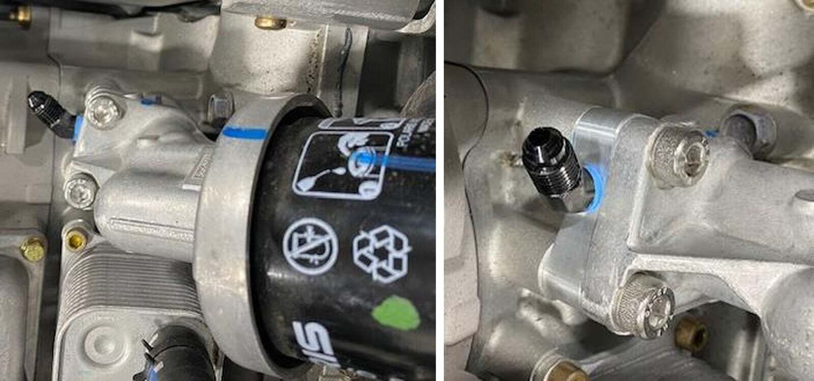
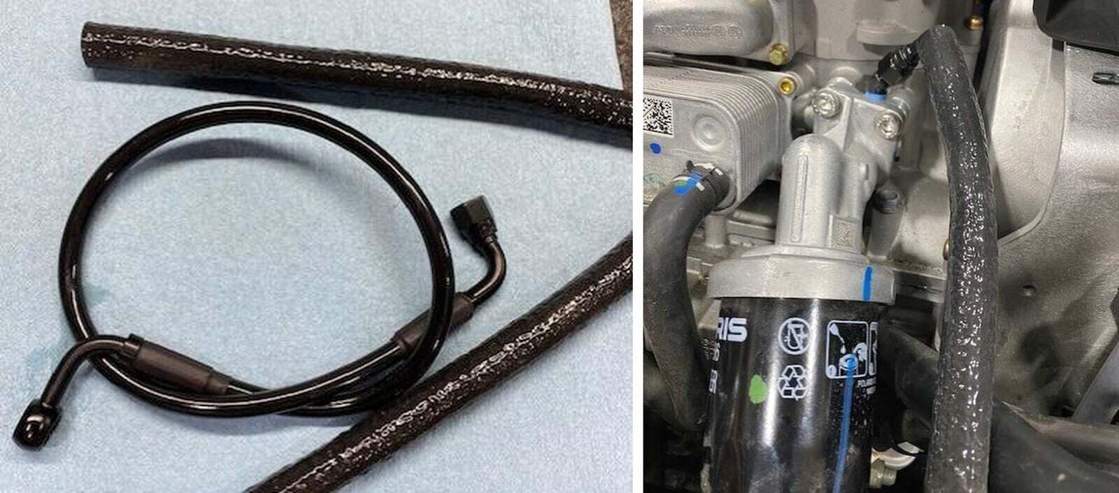
Install the fire sleeve over the soft oil feed line. Install the 90-degree fitting onto the NPT fitting located on the billet block. Keep this loose for now.
49
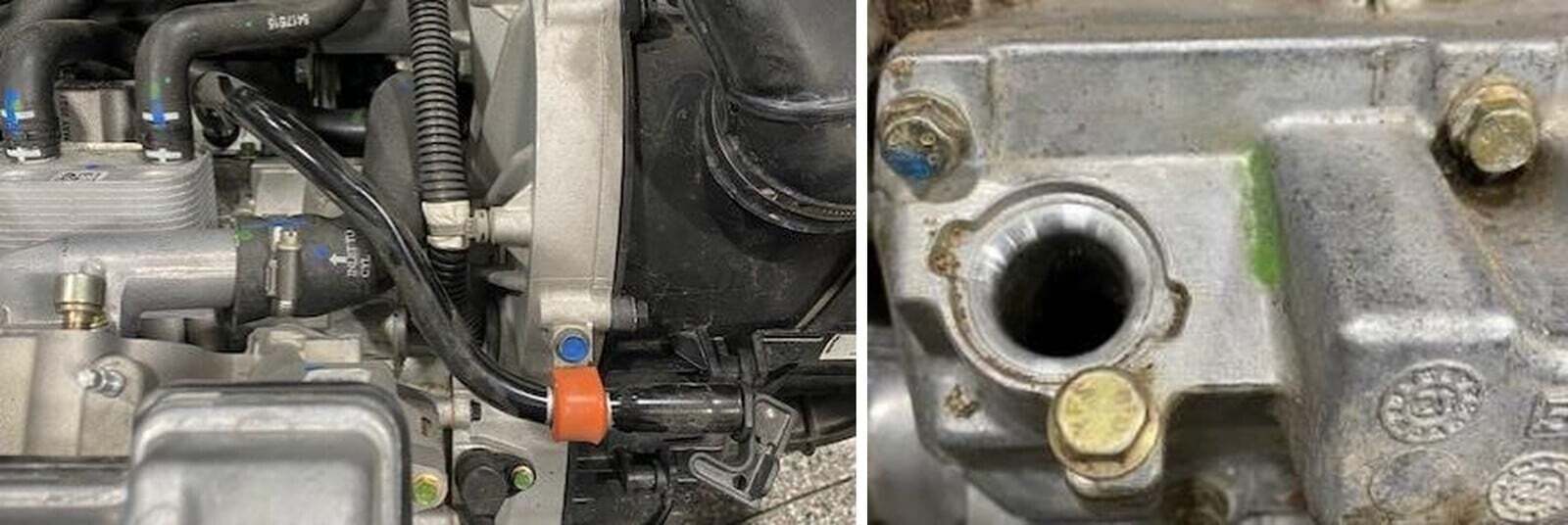
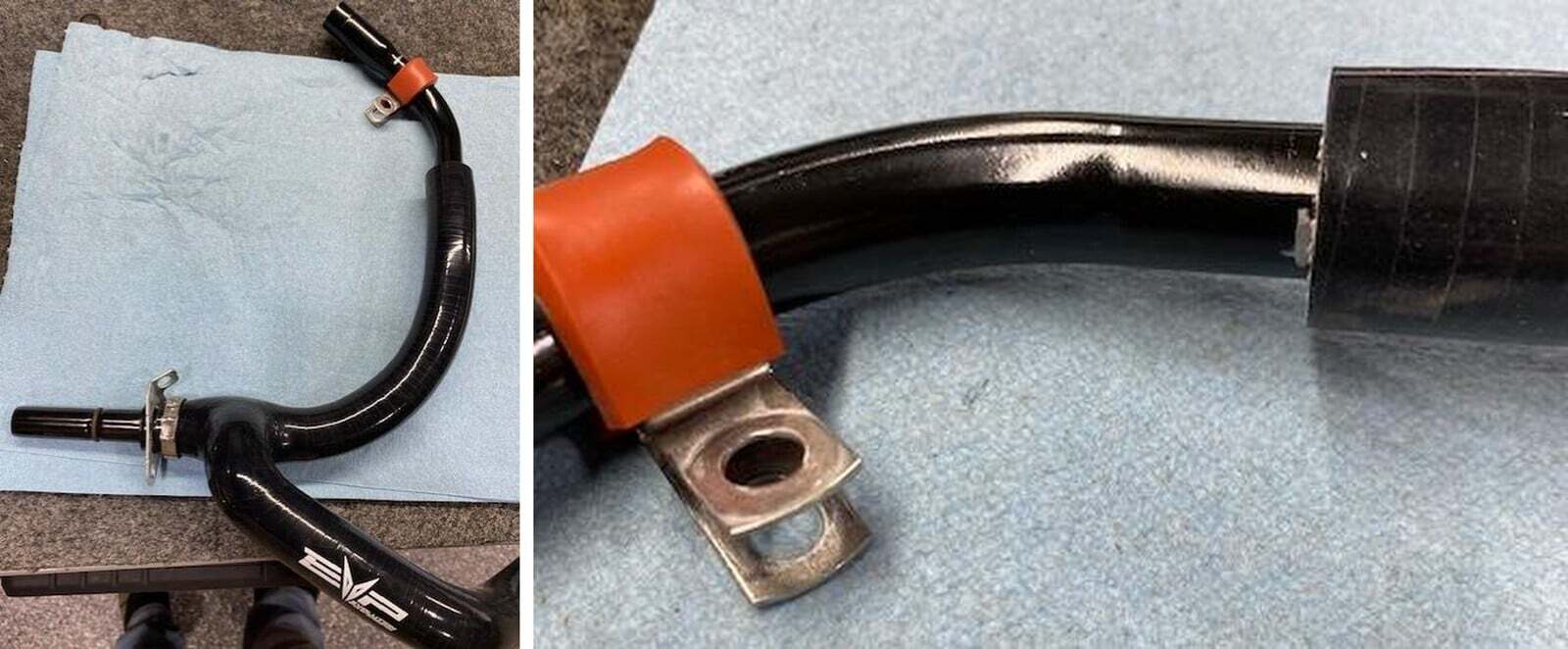
Locate the dipstick tube, read the dip stick and check the oil level. Keep the dip stick removed. With a silver sharpie mark both sides of the orange isolator. Remove the 10mm screw holding the orange rubber isolator to the alternator cover.
50
At the other end of the dipstick tube located on the engine crank case block, remove the (2) 8mm screws holding the dipstick bracket in. Spray with compressed air before removing.
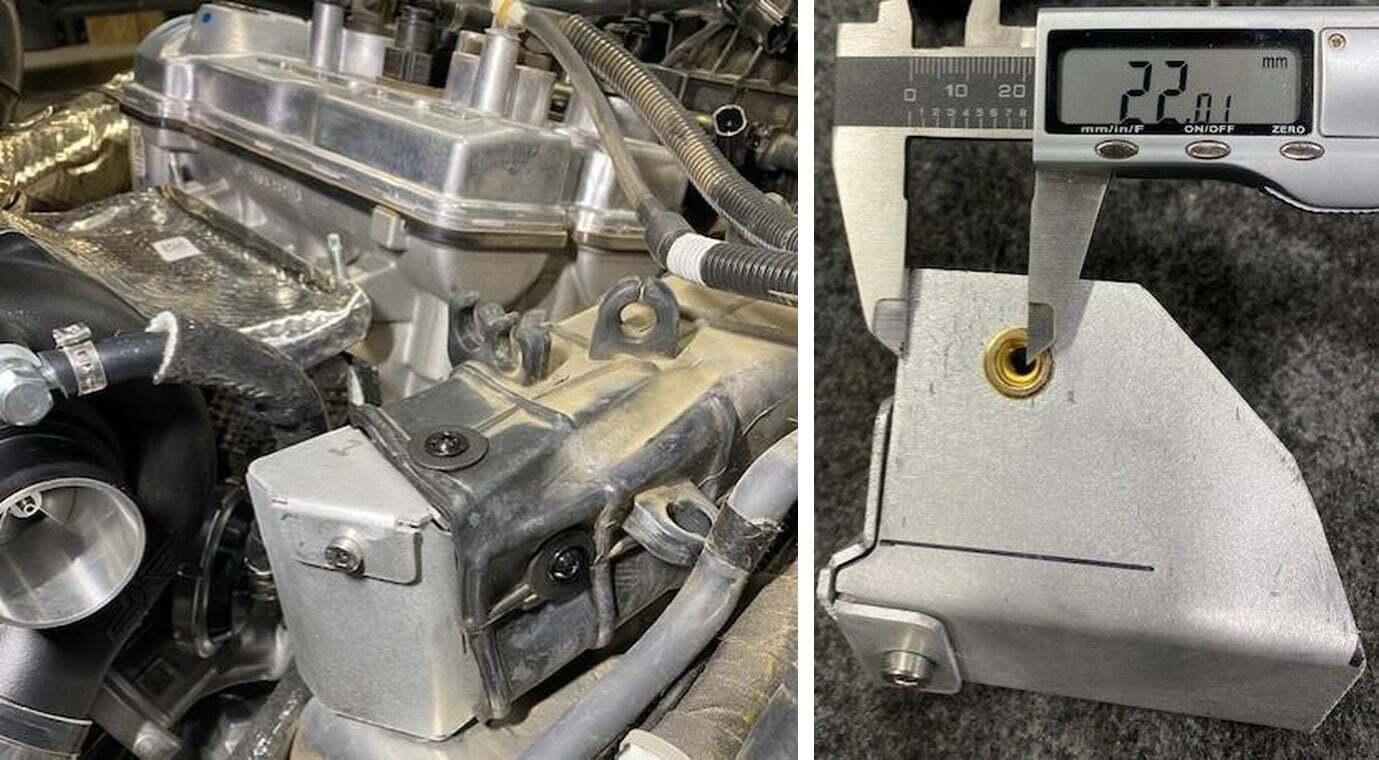
51
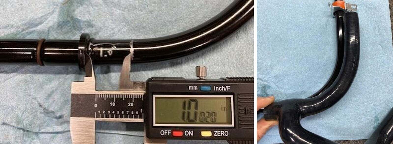
With the dip stick tube removed, measure 1.0 inch up from the lower mounting point.
52
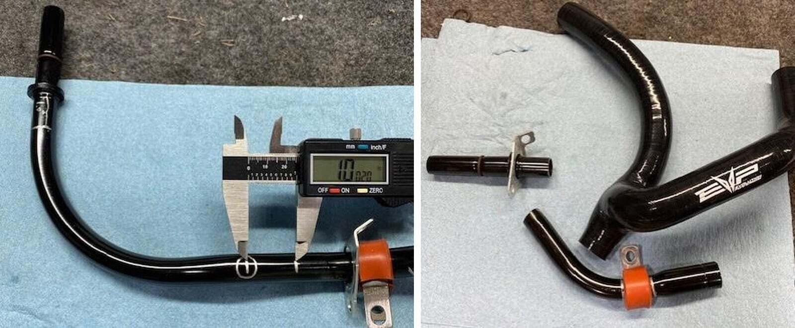
Lay the silicone dip stick tube (the longer hose without the EVP logo), over the metal dip stick tube and mark the end with a silver sharpie. Line the bottom portion onto the lower mounting point that you measured from in the last step.
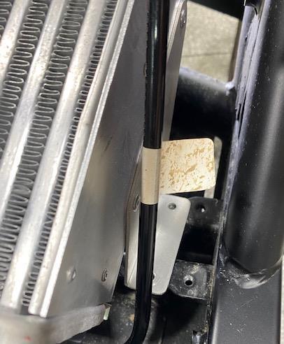
53
From the silver sharpie mark measure back 1.0 inch and make another mark (circled in the photo). You will cut the middle section out of the metal dip stick tube.
54
Cut the tube, file the sharp edges away, clean the inside of the tube VERY WELL.
55
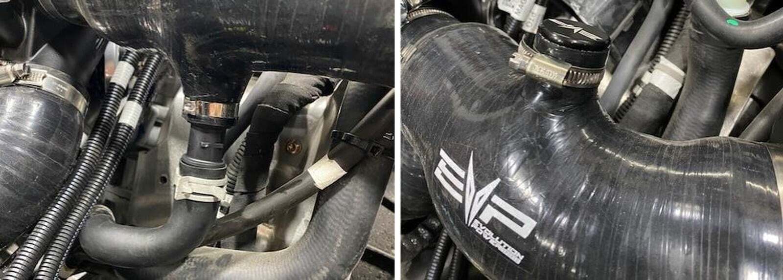
Install the lower mounting bracket onto the lower section of the tube, install it into the silicone tube with a 27mm pinch clamp. Install the upper dipstick tube and orange isolator into the upper section and secure with a 27mm pinch clamp. You may want to test fit it into the vehicle before tightening. The dip stick isolator should be in the same spot as before. Check your oil level once completed. If its not reading the same, loosen the orange isolator and push the upper tube farther into the silicone.
56
Reinstall the lower 8mm screws and upper isolator screws. NOTE: Install both 7.0” pieces of fire sleeve over the silicone on the oil drain and dip stick tube.
57
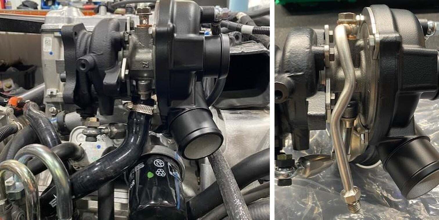
Install the turbocharger with supplied new gasket and hardware. Torque to 16 ft-lb.
58
Install the oil drain hose to the turbocharger, make sure it is all the way on without a bend in the tube. Check clearance between the oil drain hose and wastegate rod. Tighten with the supplied worm drive.
59
Remove the red plug on the oil feed side of the turbocharger, install the hard oil feed line onto the turbocharger with 2 copper washers and banjo bolt. Connect both lines by the 4an fittings and tighten down.
60
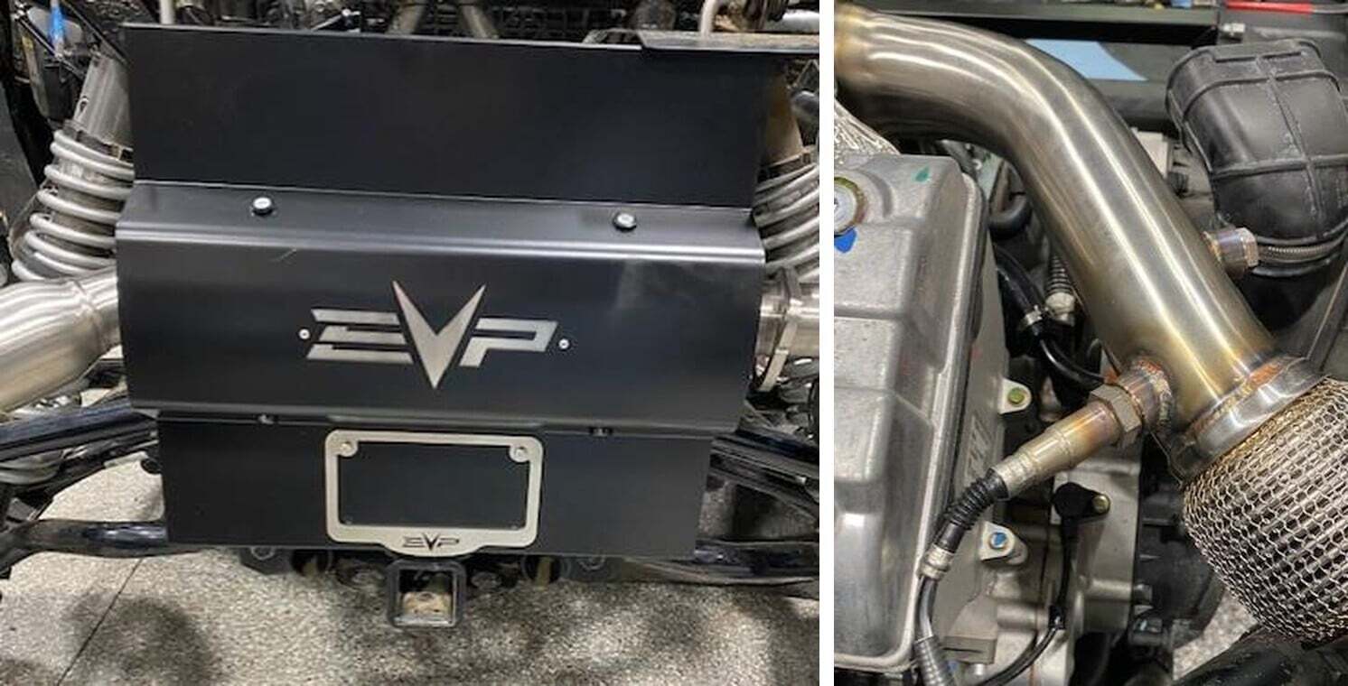
Install the lower heat shield onto the turbo. Use supplied hardware, you may need to rotate the worm drive to fit correctly.
61
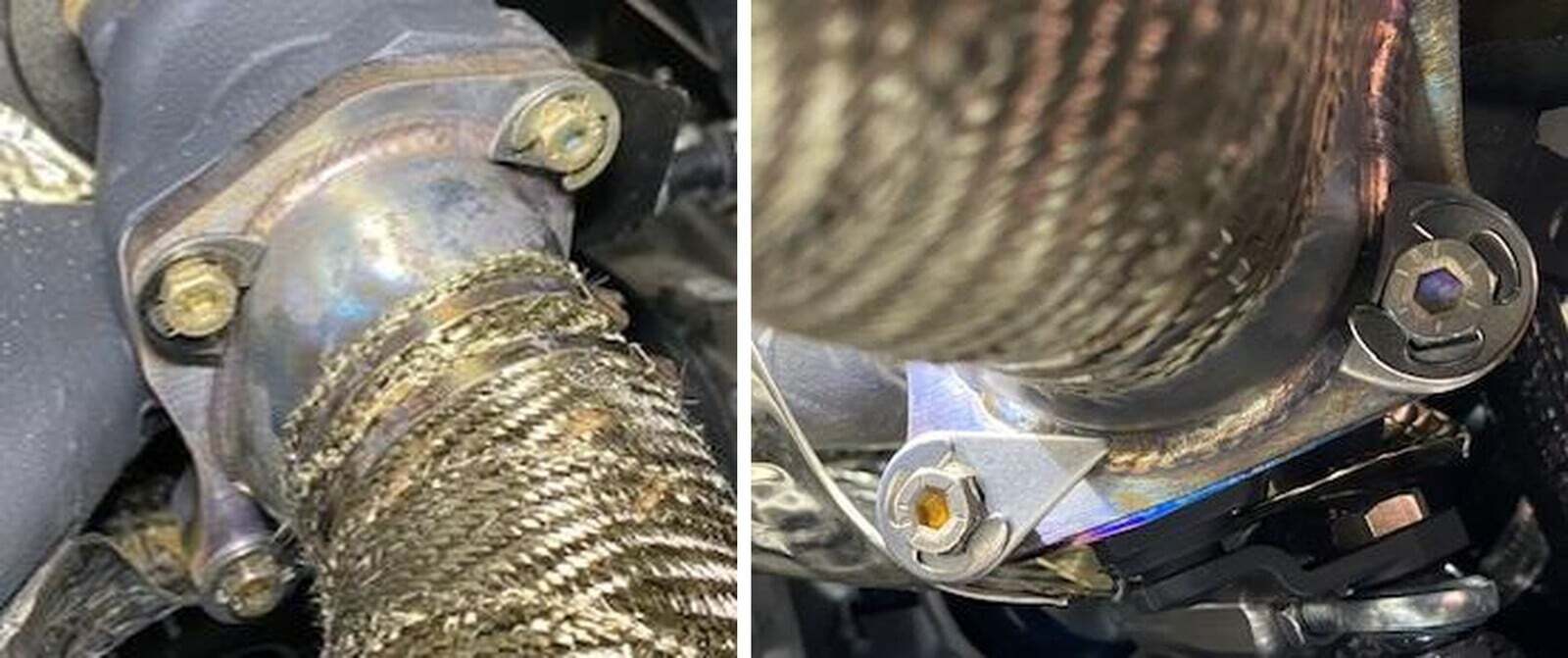
Install the downpipe with supplied gasket and hardware. Torque to 16 ft-lb. Install the Stage 8 locking fasteners. (3) half moons and (1) tear drop which will be installed on the lower left bolt.
62
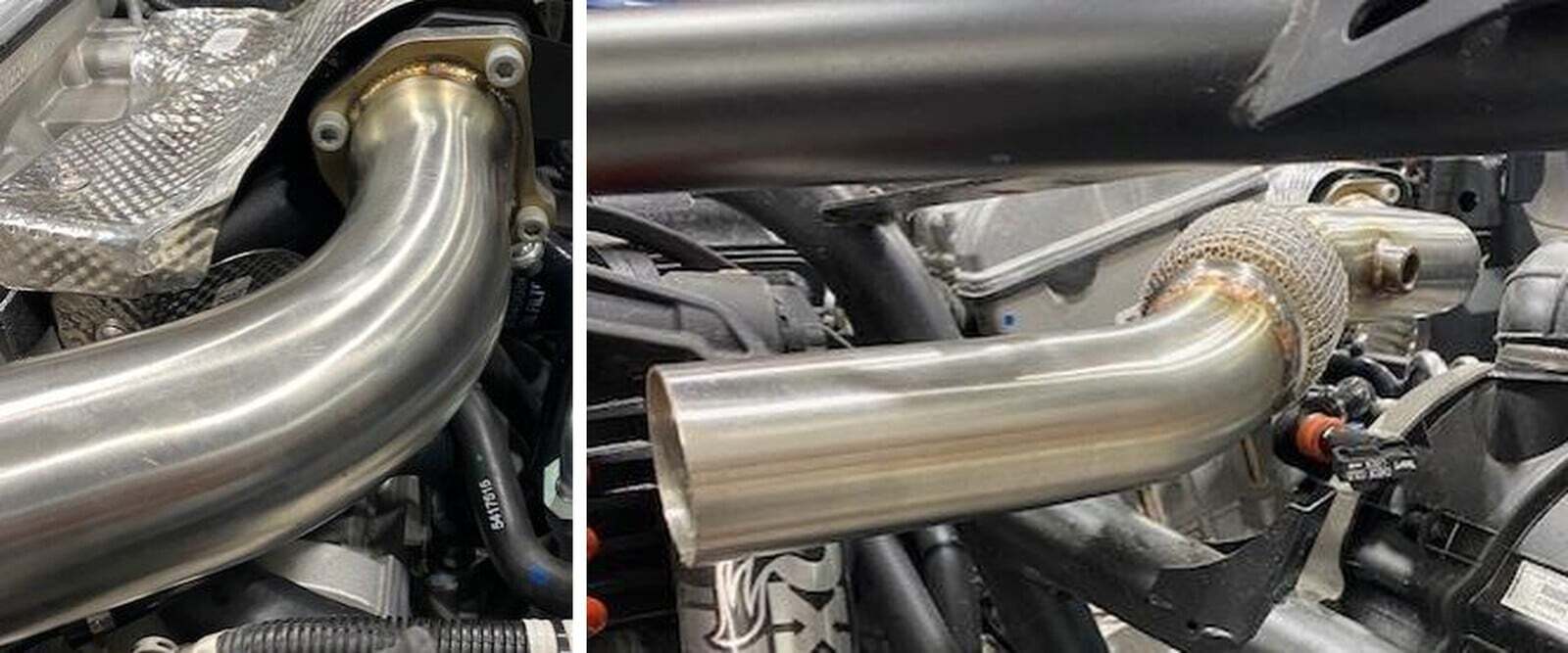
Figure Install79 the mid-pipe to the downpipe with supplied clamp. Don’t tighten clamp yet.
63
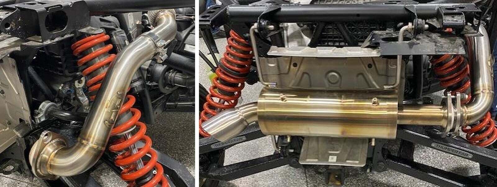
Reuse the OEM donut gasket or buy new if wrecked. Install the muffler to the (3) gromets and mid pipe. Reuse OEM hardware. Go back and tighten mid pipe clamp.
64
Cut 2.0” off the lower portion of the heat shield, install the supplied heat shield for the new muffler.
65
Install the 02 sensor into the 02 bung closest to the engine. Make sure the auxiliary bung is tight. Use anti-seize on the threads.
66
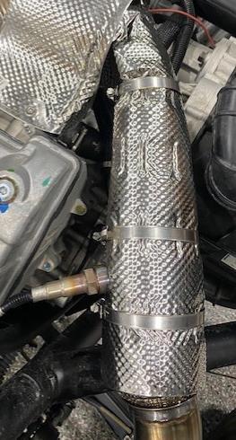
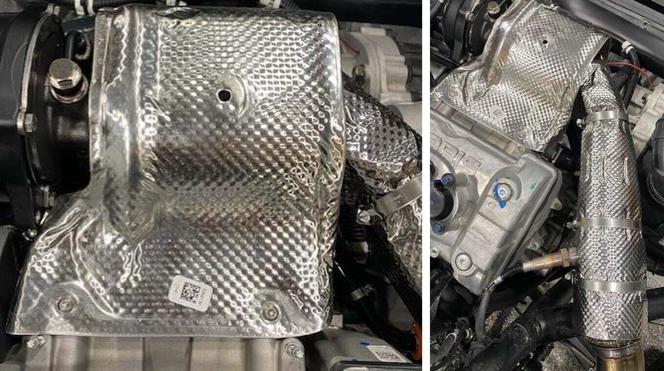
Install the downpipe heat shield, cut a small “V” on the bend. Use (2) 70/90 and (1) 40/60 worm drive to clamp.
67
Install the upper heat shield onto the turbocharger. Use supplied hardware.
68
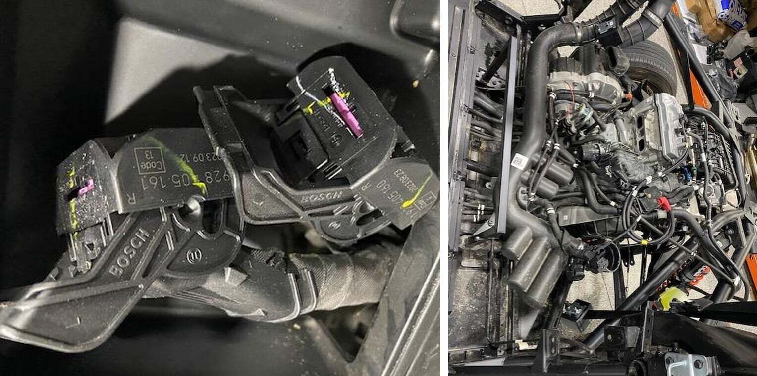
Unplug the map sensor connector and the injector(s) connector.
69
Spray around the injector ports well with compressed air. Remove the GREEN safety clip on the fuel line connector. Push in the WHITE clip and remove the fuel line from the rail. Remove the (2) T-30 screws holding the rail in.
70
Remove the fuel rail, dump the fuel out of the rail. Remove injector clips and OEM injectors. Remove the adaptors off the supplied injectors. Use dielectric on all O-rings and install into the fuel rail. Reinstall into the plenum.
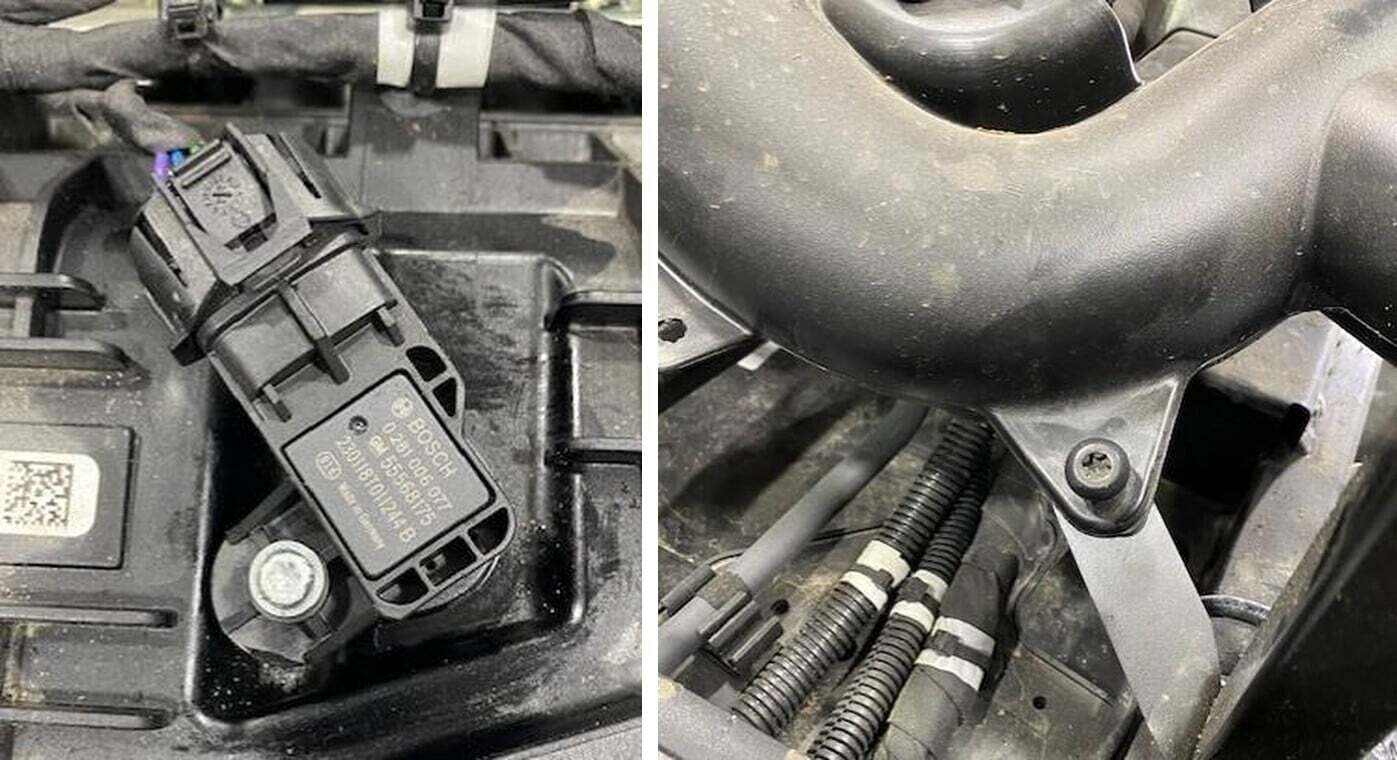
71
Remove the T-25 screw holding the MAP sensor in, apply dielectric to the new MAP sensor and install with OEM screw.
72
Remove the T-40 screw holding the fresh air duct to the frame.
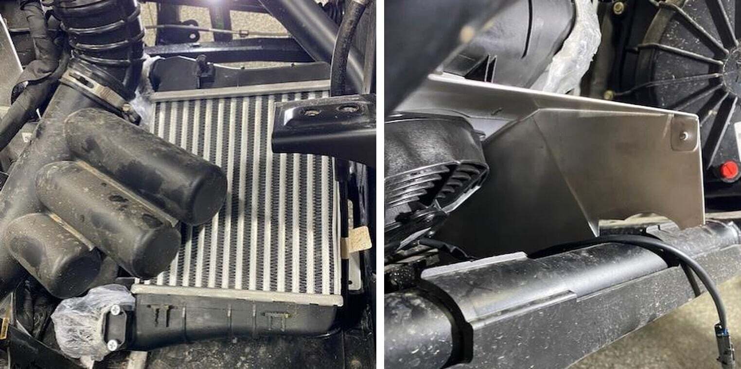
73
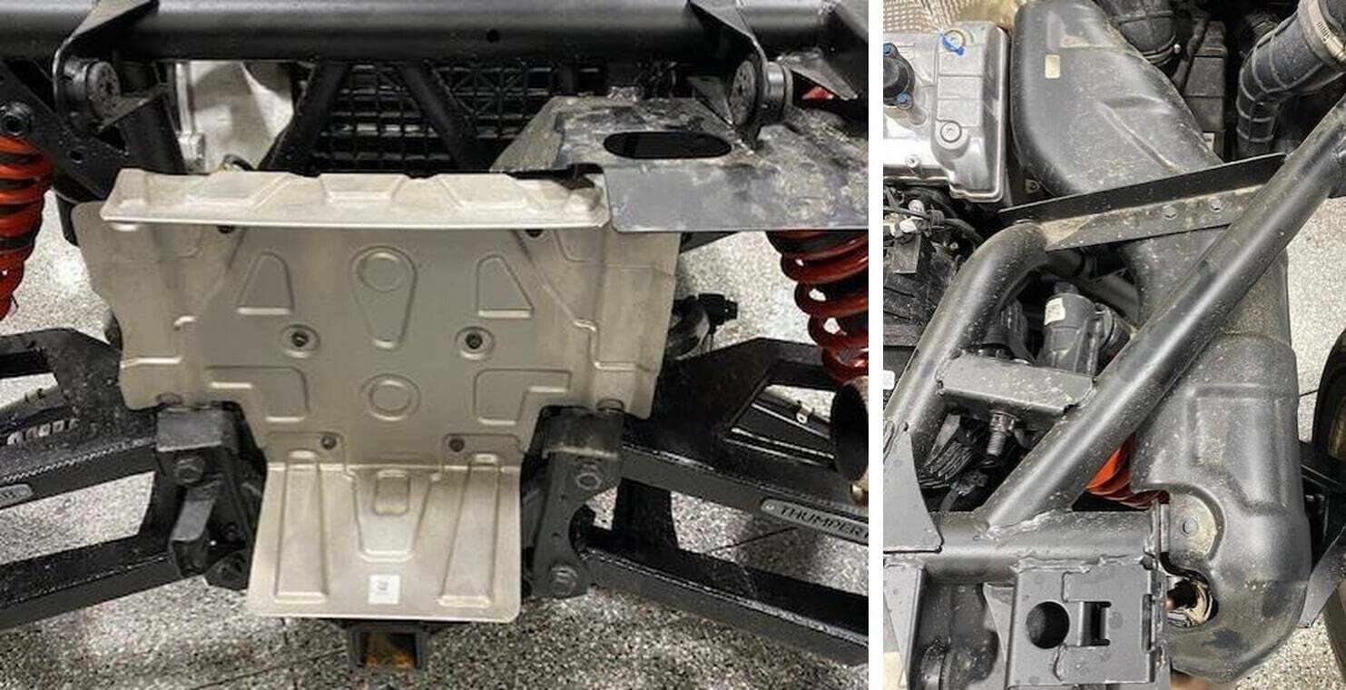
Install the intercooler assembly by the CVT box up into the frame as shown.
74
The rear lip will rest on the frame, (this is a prototype photo).
75
Mount the intercooler bracket to the frame, use supplied M6 screws.
76
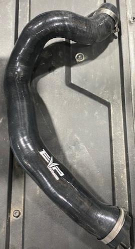
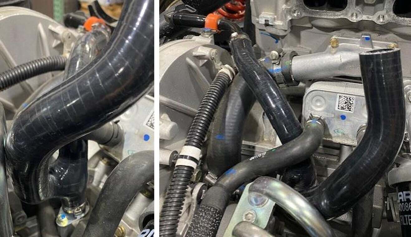
Remove the plastic bags off the intercooler inlets, install the intercooler to turbocharger tube, route underneath the OEM intake tube. Use supplied 40/60 and 50/70 clamp.
77
IF YOU ARE NOT RUNNING A BLOW OFF VALVE OR BOOST RECIRCULATING VALVE FOLLOW BELOW STEP. IF YOU ARE SKIP TO STEP 58. Install the charge tube between the intercooler and throttle body, use supplied 50/70 clamps. Install supplied 1.0” plug into the port, fasten down with 25-40 clamp.
78
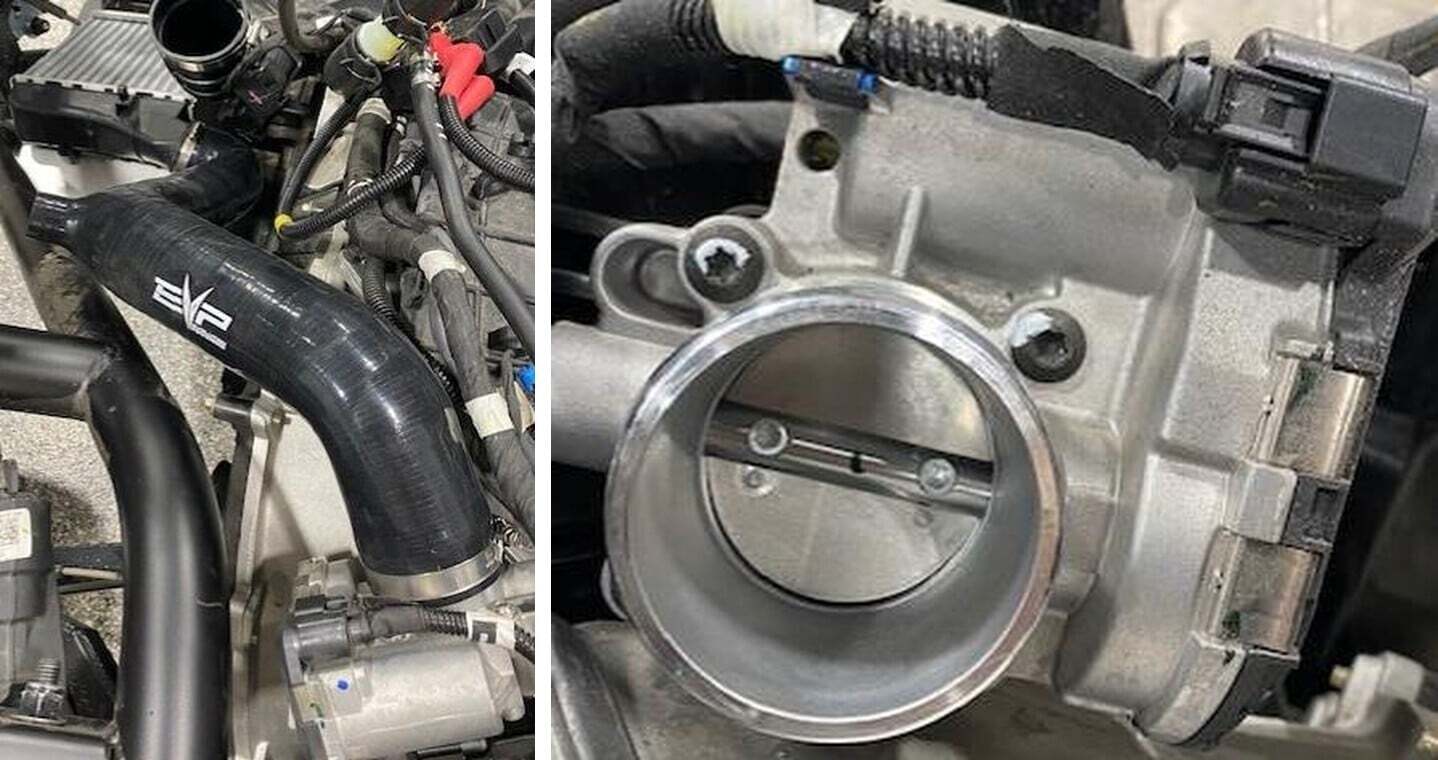
IF YOU ARE RUNNING A BLOW OFF VALVE OR RECIRCULATING VALVE. Unplug the throttle body connector and remove (4) T-30 screws holding the throttle body on.
79
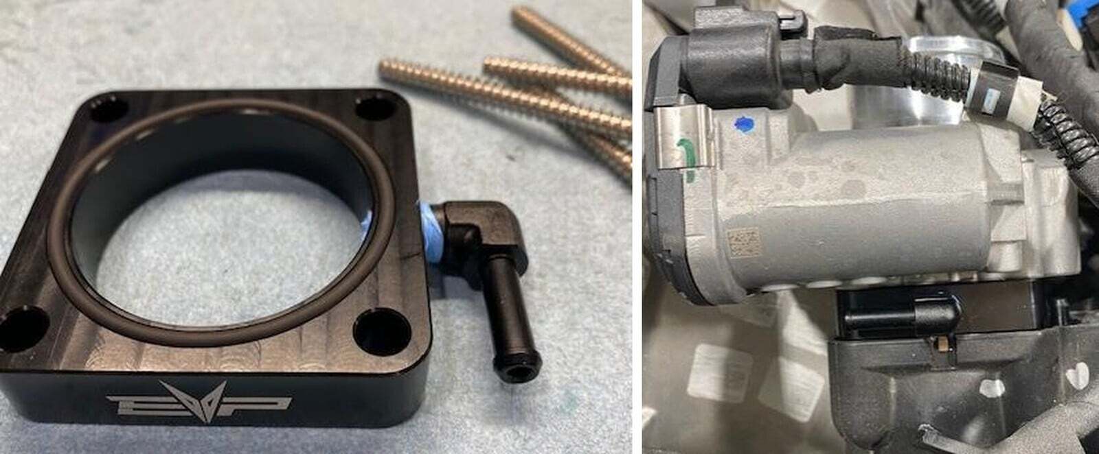
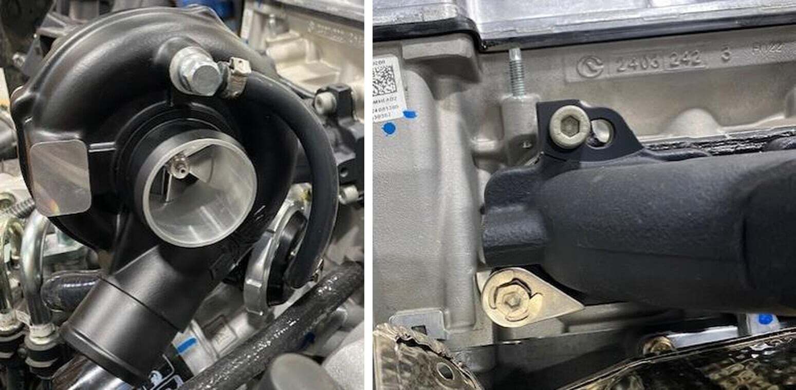
Install supplied O-ring and NPT fitting with Teflon onto the throttle body spacer plate. Make sure the barb is facing the EVP logo.
80
Install the plate and throttle body back onto the car. The plate will go against the OEM throttle body gasket, and the throttle body will mate against the O-ring on the plate. Use supplied hardware. See orientation of the barb.
81
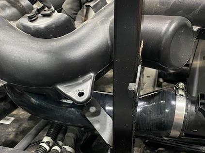
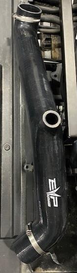
Install the charge tube between the intercooler and throttle body, use supplied 50/70 clamps.
82
BOV: Install the pre filter onto the BOV, secure with a zip tie. Install the BOV into the charge tube and fasten with a 25-40mm worm drive. Route the vacuum hose from the throttle body plate to the BOV. Use supplied pinch clamps to secure. BRV: Install the valve into the charge tube, secure it with a 25-40mm worm drive. Install the silicone tube from the BRV and secure with a pinch clamp. The other end will go into the airbox to turbocharger tube once installed. Route the vacuum hose from the throttle body plate to the BRV. Use supplied pinch clamps to secure.
83
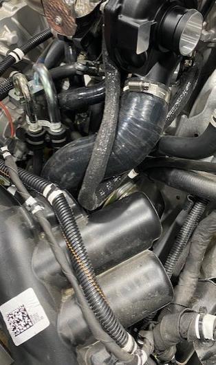
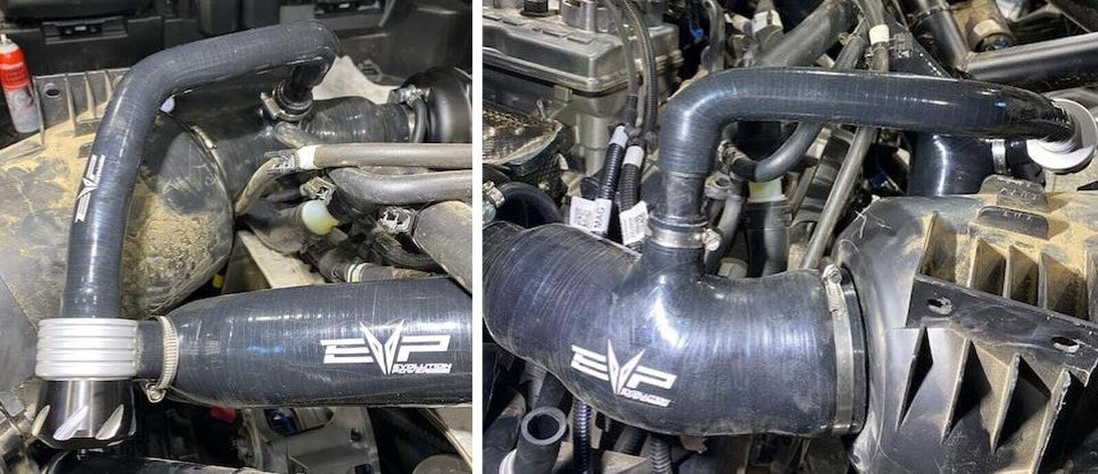
Install the airbox to turbocharger silicone onto the OEM airbox. Use supplied 40/60 and 80/100 clamps. Reinstall the airbox to the original location with the airduct installed onto the bottom. Adjust the silicone piece accordingly before tightening the clamps.
84
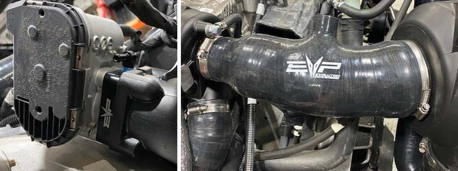
Remove the OEM crank case barb from the crank case hose. Install the supplied 3/4" barb into the crank case hose and airbox silicone. Reuse self-tightening clamp and supplied pinch clamp.
85
If you are running a BOV or nothing, plug the 1.0” port on top of the airbox silicone. If you are running a BRV, install supplied 1.0” barb and connect the BRV hose. See below.
86
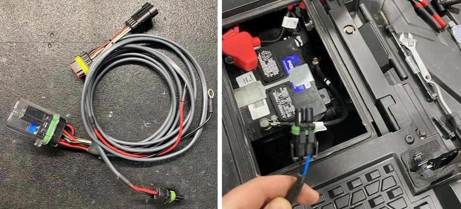
Installing the intercooler fan relay. Fuel pump Female Connector (into the Harness).
87
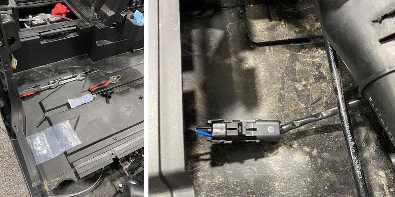
Locate the battery, fish the double connector underneath the plastic floor towards the intercooler fan.
88
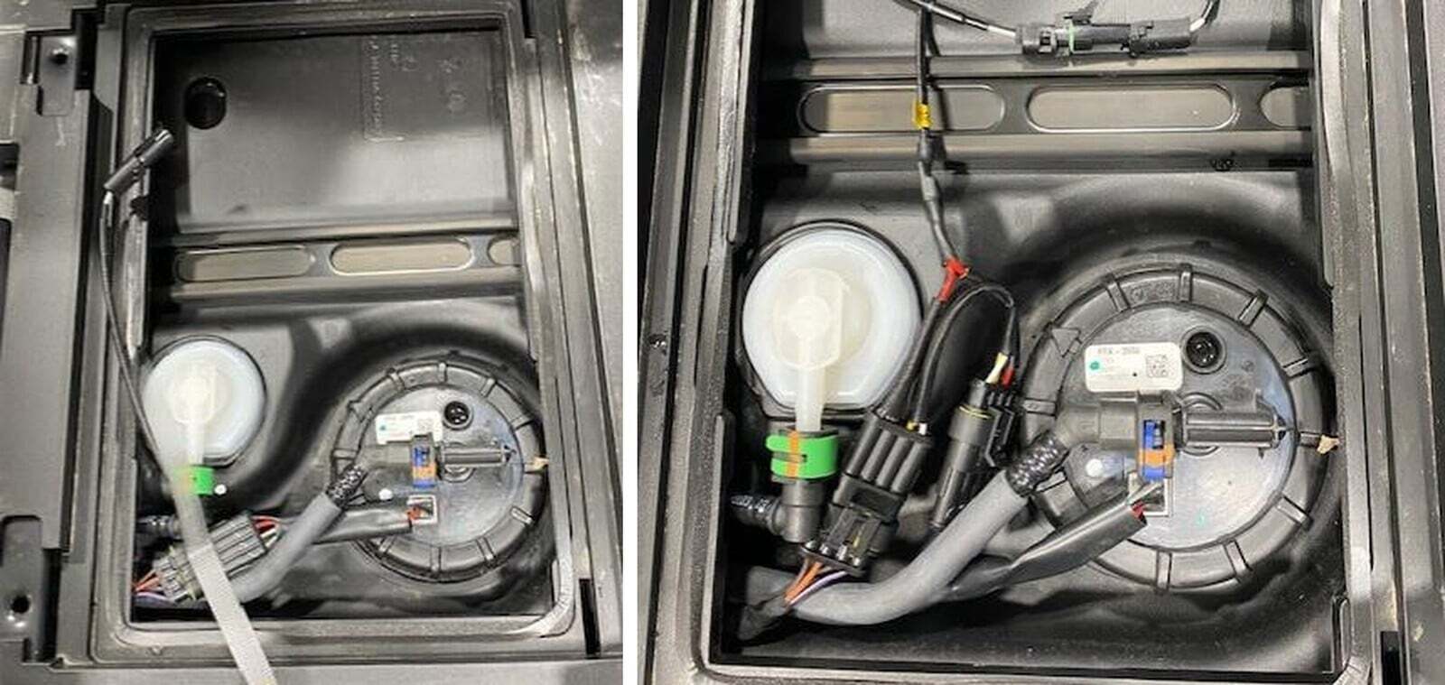
Fish the fuel pump section under the center console to the fuel pump.
89
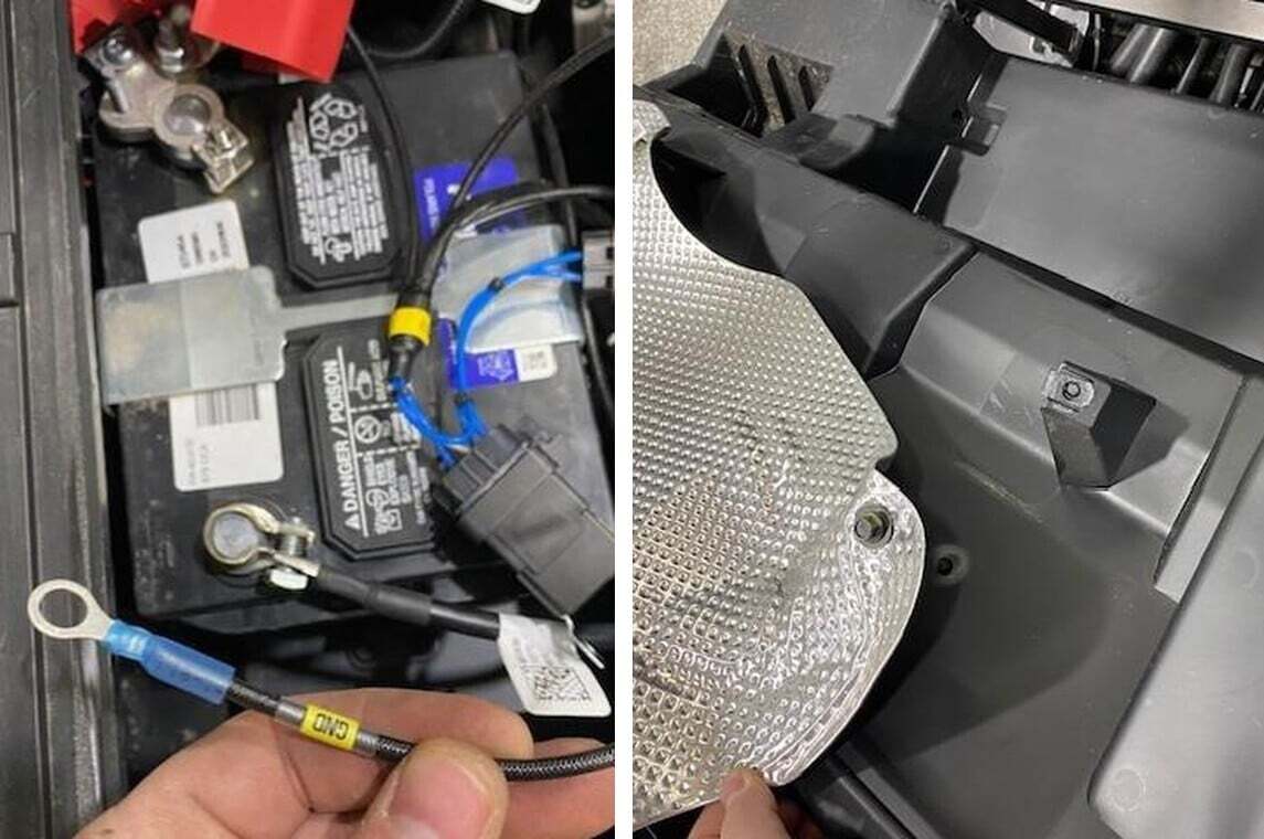
Install the relay positive and negative to the battery. The positive can be installed to the stud on the battery post, use supplied 10mm nut. The ground has a larger ring terminal, this will be connected to the bolt on the post.
90
The heat shield located on the rear of the lower firewall, remove the T-40 screw and cut the plastic stub off. Keep the heat shield installed!