Installation instructions for the Evolution Powersports 9000/1100T Big Chute Turbo on Arctic Cat 9000/1100T snowmobiles. Covers the purchase agreement, turbo removal and core-exchange shipping, Big Chute turbo installation, fuel pump installation for 100 octane kits, and initial ride setup.
9000/1100T Big Chute Turbo
AGREEMENT: By purchasing and installing this kit, you understand and agree to the following:
- THIS IS A HIGH PERFORMANCE UPGRADE!!!! ALTHOUGH WE HAVE GONE THROUGH GREAT LENGTHS TO BUILD SAFETY INTO THIS TURBO KIT, THE FACT IS THE NEW DEFAULT BOOST LEVEL IS 15LBS – NOT 7 LIKE THE FACTORY TURBO. POOR FUEL, IMPROPER SETUP OR ANY NUMBER OF THINGS THAT ARE DONE INCORRECTLY WILL DAMAGE YOUR MOTOR.
- YOU HAVE LIKELY VOIDED THE WARRANTEE OF YOUR ARCTIC CAT SNOWMOBILE
- YOU HAVE LIKELY VOIDED THE SOUND AND EXHAUST EMISSION STANDARDS OF YOUR COUNTRY
- THIS IS A PERFORMANCE UPGRADE WHICH MAY SHORTEN THE LIFE OF YOUR ENGINE, ESPECIALLY IF INSTALLED INCORRECTLY OR OPERATED WITHOUT REGARD TO YOUR INSTRUMENTS
- THE FUEL REQUIREMENTS MUST BE ADHERED TO – 93 OCTANE KITS ARE 93 OCT, NOT 91 WITH OCTANE BOOST. TO MAKE 93 OCTANE FROM 91, YOU NEED TO MIX 2.5 GALLONS OF 100 LL AVIATION FUEL WITH 8 GALLONS OF PURE 91 TO FILL YOUR TANK. IF MIXING 110 WITH 91, YOU NEED 1.5 GALLONS OF 110 TO FILL YOUR TANK. IF UNSURE OF YOUR RATIO OR FUEL QUALITY, USE MORE OF THE HIGHER OCTANE!!!! POOR FUEL CAN DESTROY A MOTOR IN SECONDS!!!
- YOU HAVE INSTRUMENTS ON YOUR SLED THAT WILL ALLOW YOU TO PERIODICALLY MONITOR AT A MINIMUM AIR/FUEL AND BOOST (ONLY DO THIS WHEN IT IS SAFE TO DO SO!!!! – YOUR FIRST OBLIGATION IS TO PAY ATTENTION TO WHERE YOU ARE GOING!!!)
- EVOLUTION POWERSPORTS BEARS NO RESPONSIBILITY FOR DAMAGE CAUSED TO YOUR SNOWMOBILE BY THE INSTALLATION OF OUR PRODUCTS. THE WARRANTEE ON OUR PARTS IS 90 DAYS FROM 1ST USE. EVOLUTION POWERSPORTS, AT ITS DISCRETION WILL DETERMINE WHETHER A PART MEETS THE WARRANTEE REQUIREMENTS. IN NO CASE IS THERE ANY WARRANTEE FROM EVOLUTION POWERSPORTS FOR YOUR SNOWMOBILE
- THE INSTALLATION OF THIS KIT IS TECHNICAL AND INVOLVED IN NATURE WITH MANY OPPORTUNITIES TO MAKE MISTAKES – MISTAKES THAT CAN BE VERY COSTLY!!! IF YOU ARE NOT QUALIFIED TO INSTALL THIS KIT, DON'T DO IT!! BRING IT TO SOMEONE WHO IS QUALIFIED TO INSTALL THE KIT.
- THIS KIT WILL MAKE YOUR SNOWMOBILE FASTER, CLIMB HIGHER AND ACCELERATE MORE QUICKLY THAN STOCK. IF YOU ARE NOT CAPABLE OF CONTROLLING THE SNOWMOBILE WITH THE ADDED PERFORMANCE, DO NOT INSTALL THE KIT.
Turbo Removal, Packing and Shipping
- Remove hood & side panels
- Remove the plastic turbo cover on the left side of the sled (it is the plastic cover that covers the intake elbow)
- Label all of the vacuum hoses connected with the turbo, intercooler and boost control
- Loosen clamp securing the intake elbow.
- Loosen clamp securing the rubber boot to the turbo inlet
- Loosen intercooler boost hose clamps (upper and lower) and disconnect hoses from intercooler and tanks.
- Disconnect the 2 small hoses from the top of the intercooler end tank
- Remove rearward intercooler brackets
- Remove intercooler (do not remove front intercooler brackets – intercooler can be removed with these brackets attached)
- Remove the rubber water line that goes from the tank to the top of the turbo. Have a 3/8" bolt handy that you insert into the end of the rubber hose. This will prevent all of the antifreeze from leaking out. Use a rubber cap on the turbo side to plug the inlet.
- Remove the 5 screws that hold on the lower heat shield
- Remove the 3 bolts that hold in the cross brace that holds the upper heat shield on. You will need to drill out the two rivets on the main spar that hold the heat shield to the main spar. You will also need to drill out the rivets that hold the very top heat shield which wraps around the main spar
- Remove the cross brace
- Remove the 10 mm bolt on the bottom of the turbo that holds the heat shield to the turbo.
- Remove the muffler
- Spray a good penetrating oil on ALL of the exhaust nuts – header pipe to engine, header pipe to turbo, down pipe, and turbo support brackets. Let it sit for an hour.
- Remove the turbo downpipe nuts and washers (outlet pipe that connects to the turbo) The upper back one can be accessed from the right side of the sled with some ratchet extensions and a universal joint. Take a picture of how these bolts and retainers are stacked. Save all items as you will reuse them
- Remove the turbo support bracket – the one behind the steering column is very difficult to remove. Although we do not recommend this, this job is made far easier by removing the steering column. If you have the vertical steering modification from Arctic Cat, you can use these instructions for the removal and reinstallation of the column.
- Remove the nuts and washers holding the header pipe on
- Using a 14 MM socket, remove the oil line from the top of the turbo. Save the bolt and two washers and be careful not to damage them!
- Remove the nuts and washers holding the turbo to the header
- Looking at the right side of the turbo (clutch side of the engine), you will see a rubber oil drain line – it is a rubber hose coming from the bottom of the engine. Using a long needle nose pliers, slide the hose clamp down, then using a screw driver, push the rubber oil drain line off of the turbo oil drain line.
- Using a long needle nose pliers and coming from the clutch side, slide the hose clamp that holds the bottom water line on the turbo so you can remove the line from the turbo. Have a 3/8" bolt handy to slide into the water line once you remove it from the bottom of the turbo so all of the anti-freeze does not leak out of the engine.
- Remove the header pipe
- Remove the water meter lines from the bottom side of the turbo – SAVE THE BOLTS AND WASHERS AND LINES –YOU WILL BE USING THEM ON THE NEW TURBO!
- Remove the oil drain line – SAVE ALL PARTS.
- Place all nuts, bolts and lines removed from the bottom of the turbo in a plastic bag and save – you will need them for the Big Chute install.
- THE WASTEGATE ACTUATOR AND ALL ITEMS ASSOCIATED WITH THE WASTEGATE MUST BE INCLUDED WITH THE TURBO.
- WITH TAPE AND A MAGIC MARKER, PLEASE WRITE YOUR NAME ON THE TURBO AND ECU. ALSO, PLEASE WRITE INCLUDE THE FOLLOWING IN THE BOX-
- Name:
- Address:
- Phone #
- Email address:
- Kit ordered:
- Fuel Requirement: (93 or 100 octane)
- Year, Make and Model of sled:
- Sled Modifications:
Carefully box up your turbo and ECU. WRAP YOUR TURBO IN A PLASTIC BAG, LINE THE BOTTOM OF THE BOX WITH A LARGE AMOUNT OF PADDING. GET A CAN OF SPRAY FOAM FROM YOUR LOCAL HARDWARE STORE AN USE IT AROUND THE TURBO. LET IT DRY. VERIFY THE TURBO WILL NOT BOUNCE AROUND. PACK THE ECU IN A PLASTIC BAG AND FOAM THIS IN PLACE AS WELL. PACK THE REST OF THE BOX WITH PADDING SO NOTHING MOVES AROUND. Your turbo and ECU must be in serviceable condition to qualify for the exchange (See next page for shipping instructions)
Ship your turbo and ecu to: Evolution Powersports 1810 Newberry Ave N Stillwater, MN 55082
Turbo Install
PUMP 91, 93 OCTANE/100 OCTANE
- It is best to put a clean paper towel into the intake side and intake outlet side of the turbo to prevent debris from entering the turbo inlet and outlet – make sure you remove them before final hose connections are made
- A few modifications will need to be made to the oil drain line and water lines prior to installation. Please refer to the pictures below:
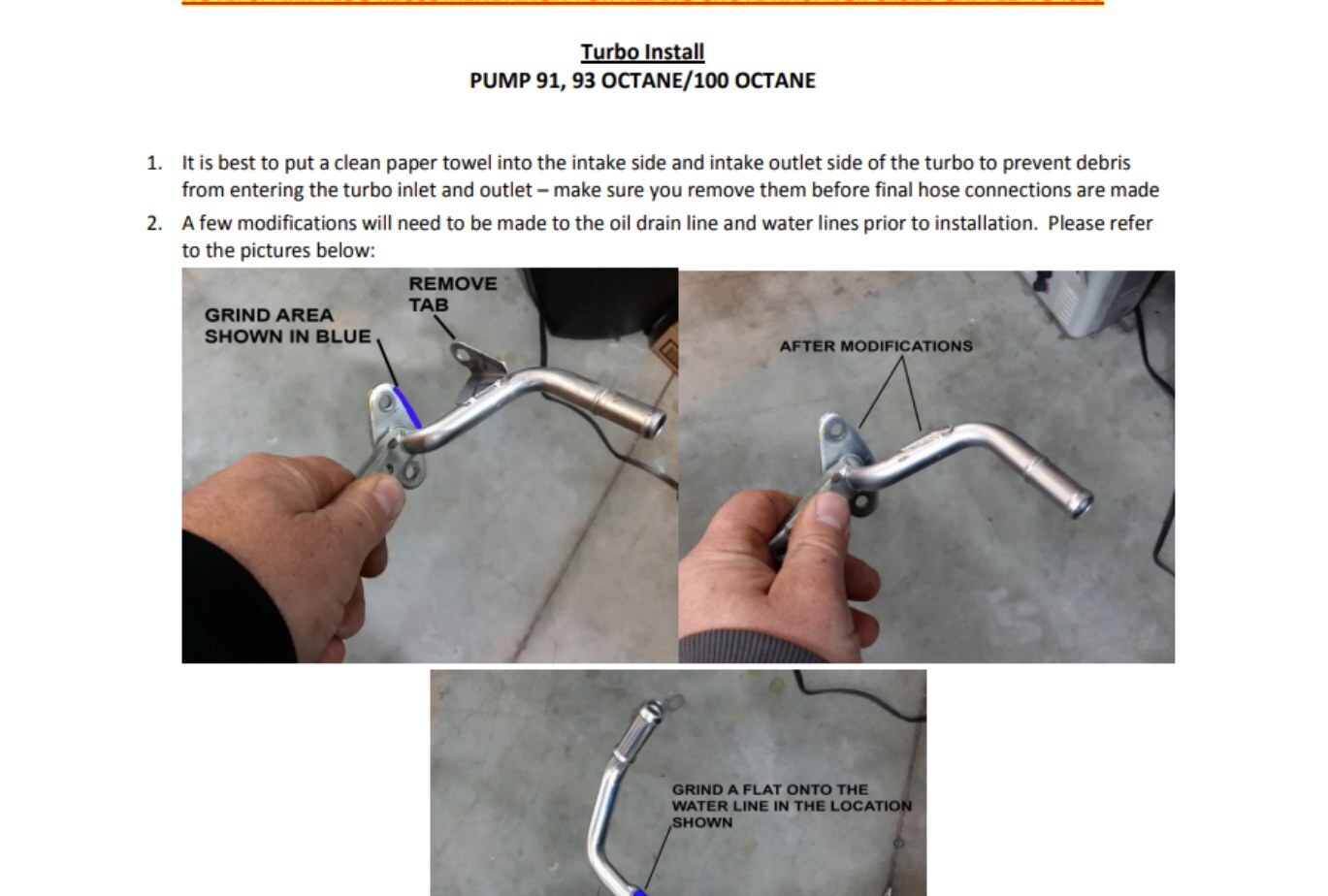
- Prep the Big Chute turbo by installing the hard water lines, hard oil drain line and vacuum line from the waste gate actuator to the turbo outlet. Refer to the picture taken in step 20 of the removal. For the water lines – install one washer below each of the banjo fittings and one above, then slide the bolt through and tighten
- Do NOT adjust the waste gate – it has been set by us and should not be changed
- Install all items in reverse above. Double check your work – make sure all clamps are on tight.
- Make sure the turbo oil supply line is installed properly – it requires one washer above and one washer below the banjo fitting. The oil line has a tight fit between the coolant lines and the waste gate bracket. You may have to bend the oil line to center it over the oil hole on the turbo. Do this carefully – do not kink the line or cross thread the bolt. Take your time. The coolant line may need a little grinding on the boss where it enters the banjo. The line is about 3/16 of an inch thick at this point. If needed, the water line boss can be ground down so the oil line does not touch. See below.
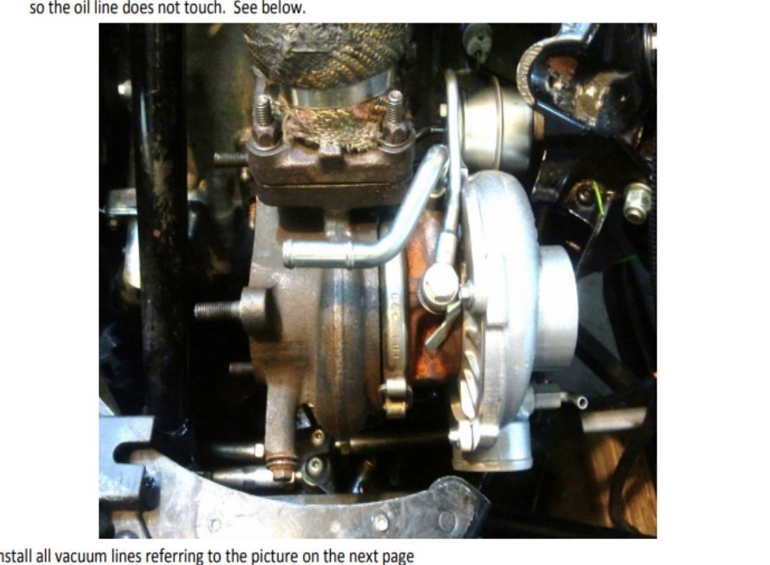
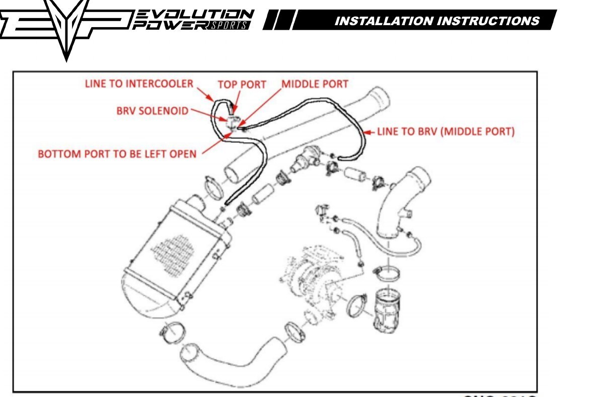
Install all vacuum lines referring to the picture on the next page
- You may have to change the clocking of the EVO supplied intake boot so the hood fits properly
- Fill coolant tank with 50/50 antifreeze. PUMP GAS KITS SKIP TO STEP 1 BELOW
100 OCTANE KITS — FUEL PUMP INSTALLATION
Fuel pump installation: (FIRE HAZARD – It is best to do this job when the tank is empty to minimize fire risk) Have a fire extinguisher handy.
- Remove cowl that covers the fuel tank. There are two torx screws on the top side and a ring around the fuel filler neck that must be removed to allow the cowl to come off.
- The fuel pump is located in the fuel tank. The access to the pump is on the top of the fuel tank on the right hand side. It is the 4" circular access cover with six torx screws arranged in a circular pattern. Disconnect the connector that has wires that go into the access cover. Disconnect the fuel fitting which is connected to the access cover. You can do this by using a needle nose pliers or circlip pliers to expand the plastic retainer. Once they are expanded, you can push the fuel line off. Remove the six torx screws and remove the entire fuel pump and fuel pickup assembly.
- TAKE A PICTURE OF THE ORIENTATION OF THE LINES AND PICKUP TO AID IN REASSEMBLY!
- Cut the clamp that holds the fuel line to the bottom of the fuel pump and pickup.
- Cut the wire tie that holds the fuel line to the bracket and set aside fuel line and fuel pickups.
- Using a flat blade screwdriver, pry up the retainer that locks the upper and lower halves of the fuel pump holder and rotate in the direction of the open slot. When the retainer clip is pushed up, the two halves will rotate freely, so don't force it.
- Pull pump down out of the upper half and remove wires from pump
- Remove short section of hose that is on the top of the factory fuel pump and install this on the new pump.
- Using a die grinder, grind enough material off of the fuel pump hanger bracket (metal bracket that has the fuel gauge float assembly attached to it) to allow the new fuel pump aluminum inlet to fit in the hanger. See Picture series below
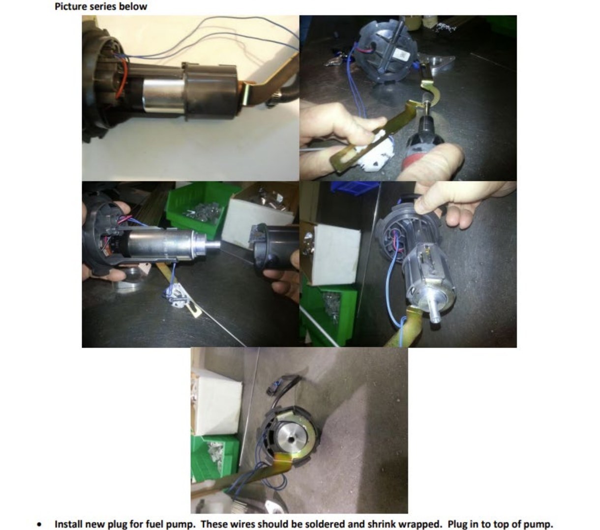
- Install new plug for fuel pump. These wires should be soldered and shrink wrapped. Plug in to top of pump.
- Reassemble pump holder halves.
- Reconnect fuel line and pickup assembly – install supplied clamp on the hose barb at the bottom of the fuel pump
- Install a new zip tie on the fuel line as it was before.
- Reinstall pump assembly into tank. This is tricky. You will know that it is in correctly when you can install everything and there is no resistance when you rest the fuel pump access cover onto the tank – in other words, everything will fit and the cover will not be pushing up. The two rear pickups have specific places where they need to be. If they are not in these spots, the assembly will have resistance. It is easier to get them in the right spot when the fuel tank is empty.
- Reinstall the six torx screws and reconnect the electric connector.
- Switch the key to the "on" position and turn the kill switch "off" you should hear the fuel pump come on for about 2 seconds, then shut off. This is normal. If you don't hear the fuel pump, there is a problem and double check your work.
- Switch key "off"
- Take the fuel return line out of the top left side of the tank. Cut the clamp that secures the fuel line to the plastic elbow.
- Remove fuel line from elbow and rubber grommet from plastic elbow.
- Place elbow in a vise with the larger end facing up. Using an 11/64 drill bit, using a marker, mark from the point of the drill 26mm down. Drill the plastic elbow from the top of the large opening that is facing up exactly to your line on the drill bit (26mm down). (DO NOT DRILL TOO FAR OR YOUR BIT WILL COME OUT OF THE ELBOW AND RUIN THE ELBOW) The purpose of this is to drill out the restrictor in the elbow to accommodate the larger fuel pump.
- Reinstall the elbow into the return line. Secure with supplied constant tension clamp and put rubber grommet back on. Reinstall in fuel tank.
- Continue with step 1 below
- Add 50/50 coolant to the overflow tank until full – leave the cap off of the tank for now.
- Loosely install the hood so it can be moved around for access to the engine coolant bleed screw on the engine and the coolant fill tank cap and reconnect the wiring enough so the engine can be started.
- Do not install the side panels at this time
- Install the EVO reflashed ECU.
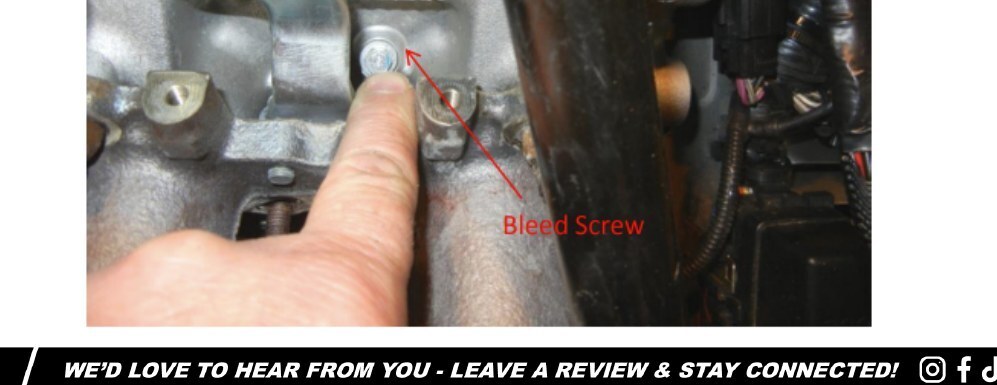
- Raise the front of the sled so the engine bleed screw (See the picture below) is higher than the rear heat exchanger.
- Start the engine for 15 seconds and shut off - check for leaks. If no leaks are detected, proceed to next step.
- Add more 50/50 coolant to the overflow tank and replace tank cap.
- Start the engine. Crack the bleed screw so a small very small amount of antifreeze can seem coming out. Let the motor idle until you can feel the rear heat exchanger getting hot. Tighten the coolant bleed screw on the engine and shut the motor off. See picture below.
- Let the engine completely cool down. Refill the coolant tank to the top.
- Start engine again, verify that the rear heat exchanger gets warm after idling for 5-7 minutes.
- Install the hood and side panels and all other items removed and tightened or loosened.
Initial Ride
- Fuel requirements are crucial. If you have a pump gas kit, good 93 Octane, non-oxygenated pump gas is REQUIRED. If only 91 Octane fuel is available, mix in 2.5 gallons 100LL aviation fuel per tankful. If running a race gas kit, the Octane required is 100. This is standard 100LL aviation fuel.
- If you have a Sno Pro with the deluxe gauge, you can monitor coolant temperatures by switching the key on and kill sw off so the display is illuminated. Push in and hold the two left hand buttons for 10 seconds. You will see the voltage appear on the bottom of the screen. Push the upper button until you see a "3" on the bottom left. Just to the right of the "3", the water temperature will be displayed. Monitor this as you ride. If the snow conditions are decent, it should NEVER exceed 200 deg F. If it does, the cooling system is airlocked. Do NOT ride the snowmobile!!! Re bleed the system. If temperature remains constant and below 195, proceed riding. Check periodically for leaks.
- If you do not have a snow pro, periodically check the rear heat exchanger. It should be very warm to the touch. Monitor the gauges for the temperature light to come on. Once you have ridden a few miles with no codes, stop and check for leaks. If no leaks are detected, proceed.
- It is assumed that your sled has a Mechanical boost gauge and an AFR gauge. These instruments are necessary for high performance aftermarket modifications. They will also help us to diagnose problems if you have any.
If you have trouble with the install or running issues, please contact our technical support department at 970-680-EVO1 (3861) or the dealer who the kit was bought from.
Note: This product is exempt from the emission standards and related requirements of 40 C.F.R. § 1051 as provided by 40 C.F.R. § 1051.620, and California law [e.g., vehicle code§§ 27156 and 38391]. This product is sold only for use in connection with EPA certified, purpose-built, nonroad vehicles used solely for closed course, nonroad competition/racing and not used for any recreational purpose or on public highways or right of ways maintained by and open to the public. This product is sold only in connection with machines that do not fall under state and/or federal noise or emission standards/regulations. Purchasers who/that purchase this product represent and warrant that the product is purchased only in connection with EPA -certified, emission-regulations-exempt and noise-regulations-exempt competition/racing vehicles as interpreted under applicable state and/or federal law. Questions: Call Evolution Powersports at (715) 247-3862.