Installation guide for the EVP 9000/1100T Super Chute Turbo on the Arctic Cat snowmobile platform. This is a turbo core-exchange kit — you remove and ship your stock turbo to EVP. Read the full agreement and all steps before starting.
Before You Begin — Please Read
- This is a high-performance upgrade. We have gone to great lengths to build safety into this kit, but the fact is the default boost level is 15 lbs — not 7 like the factory turbo. Poor fuel, improper setup, or work done incorrectly can damage your motor.
- You have likely voided the warranty of your Arctic Cat snowmobile.
- You have likely voided the sound and exhaust-emission standards of your country.
- The fuel requirements must be adhered to — 93-octane kits are 93 octane, not 91 with octane boost. To make 93 from 91, mix 1.5 gallons of 100LL aviation fuel with 8 gallons of pure 91 to fill your tank. If mixing 110 with 91, you need 1.5 gallons of 110 to 9.0 gallons of pure 91. If you are unsure of your ratio or fuel quality, use the higher octane. Poor fuel can destroy a motor in seconds.
- You must have instruments on your sled that let you reliably monitor at minimum boost pressure (only when it is safe to do so) — your first obligation is to pay attention to where you are riding.
- Evolution Powersports bears no responsibility for damage caused to your snowmobile by the installation of our products. The warranty on our parts is 90 days from first use; EVP at its discretion determines whether a part meets the warranty requirements. In no case is there any warranty from EVP for your snowmobile.
- The installation of this kit is technical and mechanical in nature, with many opportunities to make costly mistakes. If you are not qualified to install this kit, bring it to someone who is.
- This kit will make your snowmobile faster, climb higher, and accelerate more quickly than stock. If you are not capable of controlling the increased performance, do not install the kit.
Turbo Removal, Packing & Shipping
- Remove the hood and side panels.
- Remove the plastic turbo cover on the left side of the sled (the plastic cover over the intake elbow).
- Label all of the vacuum hoses connected to the turbo, intercooler, and boost control.
- Loosen the clamp securing the intake elbow.
- Loosen the clamp securing the rubber boot to the turbo inlet.
- Loosen the intercooler boost-hose clamps (upper and lower) and disconnect the hoses from the intercooler end tank.
- Disconnect the 2 smaller hoses from the top of the intercooler end tank.
- Remove the rearward intercooler brackets.
- Remove the intercooler (the front intercooler brackets can stay attached — the intercooler comes out with them on).
- Place a catch pan under the snowmobile, then remove the rubber water line that runs from the tank to the top of the turbo.
- Remove the 5 screws that hold on the lower heat shield.
- Remove the 3 bolts holding the cross brace that retains the upper heat shield. Drill out the two rivets on the main spar that hold the heat shield to the spar, and drill out the rivets holding the very top heat shield that wraps around the main spar.
- Remove the cross brace.
- Remove the 10 mm bolt on the bottom of the turbo that holds the heat shield to the turbo.
- Remove the muffler.
- Spray a good penetrating oil on ALL exhaust nuts — header-to-engine, header-to-turbo, downpipe, and turbo support brackets. Let it sit for an hour.
- Remove the turbo downpipe nuts and washers (the outlet pipe that connects to the turbo). The upper back one can be reached from the right side of the sled with ratchet extensions and a universal joint. Note how the bolts and retainers are stacked, and save all hardware to reuse.
- Remove the turbo support bracket. The one behind the steering column is difficult; although not required, the job is far easier if you remove the steering column. If you have the Arctic Cat vertical-steering modification, use their instructions to remove and reinstall the column.
- Remove the nuts and washers holding the header pipe on.
- Using a 14 mm socket, remove the oil line from the top of the turbo. Save the bolt and two washers and be careful not to damage them.
- Remove the nuts and washers holding the turbo to the header.
- On the right (clutch) side of the engine, find the turbo oil-drain line — a rubber hose from the bottom of the engine. With long needle-nose pliers slide the clamp down, then with a screwdriver push the rubber oil-drain line off the turbo drain.
- From the clutch side, with long needle-nose pliers slide the clamp off the lower water line and remove the line from the turbo.
- Remove the cross brace and the turbo.
- Remove the hard water lines and the oil-drain line from the turbo — SAVE the oil-drain line; you will reuse it on the Super Chute turbo. The wastegate actuator and all wastegate hardware MUST be included when you send your turbo to us as a core.
- With tape and a marker, write your name on the turbo and the ECU, then include the packing-list information below in the box.
Carefully box up your turbo and ECU: wrap the turbo in a plastic bag, line the bottom of the box with padding, verify the turbo will not bounce around, pad the ECU in a plastic bag, and pack the rest of the box so nothing moves. Your turbo and ECU must be in serviceable condition to qualify for the exchange. Include in the box:
- Name
- Address
- Phone #
- Email address
- Kit ordered
- Fuel requirement (91, 93, or 100 octane)
- Year, make, and model of sled
- Sled modifications
- Any previous ECU modifications
Turbo Install — Turbo Prep
- Put a clean paper towel into the intake side and intake-outlet side of the turbo to keep debris out — remove them before making final hose connections. Do NOT adjust the wastegate; it has been set by us and should not be changed.
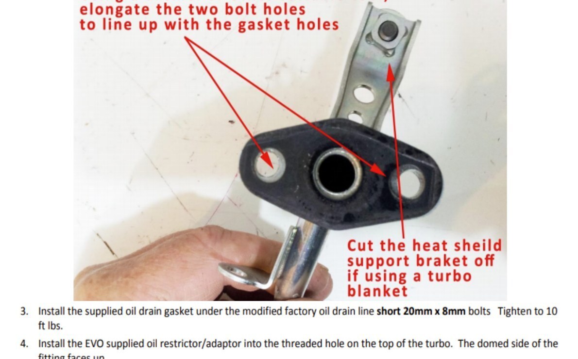
- Reuse the oil-drain line that came off the stock turbo; it must be modified for the Super Chute turbo. Using the supplied new oil-drain gasket as a template, line up the drain hole in the gasket with the factory drain hole. The factory bolt holes will not fully line up, so mark and elongate the holes in the factory drain-line flange so it bolts to the Super Chute turbo.
- Install the supplied oil-drain gasket under the modified factory drain line using the short 20 mm × 8 mm bolts. Tighten to 10 ft-lb.
- Install the EVP-supplied oil restrictor/adaptor into the threaded hole on top of the turbo — the domed side of the fitting faces up.
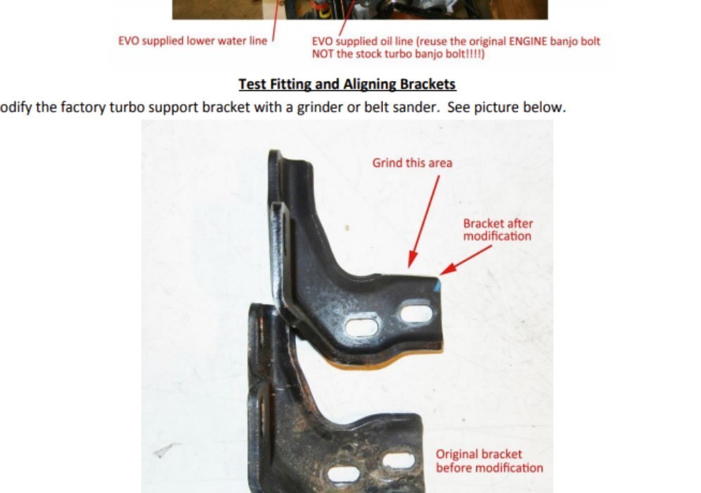
Engine Prep & Test-Fitting
- Remove the factory U-shaped water line from behind the oil filter and replace it with the EVP-supplied molded hose, matching the curve of the factory hose. If the hose is hard to slide on, spray brake cleaner into the end. Reuse the factory constant-tension clamp to secure it.
- Remove the factory hard oil line from the engine. Install the EVP-supplied oil line using the banjo bolt and washers (do NOT use the band bolt from the factory turbo); place a washer on each side of the banjo fitting and tighten to 10 ft-lb.
- The turbo install is easier if you remove the chassis round spars and steering spar bar; if you do, refer to the shop manual for reinstallation after the kit is installed.
- Modify the factory turbo support bracket with a grinder or belt sander (see photo).
- Install the SC exhaust gasket and up-pipe onto the turbo outlet flange. Install the supplied 30 mm bolt and stud into the top middle threaded hole on the exhaust flange of the turbo; install the front and bottom nuts. Use the supplied 10 mm × 1.25 copper nuts and washers on the stud. Tighten all nuts and bolts.
- Install the EVP-supplied steel turbo support bracket onto the 45 mm bolts sticking through the turbo outlet flange. Using the supplied M10 × 1.25 copper nut, secure the bracket onto the turbo — refer to the picture in step 13 for orientation.
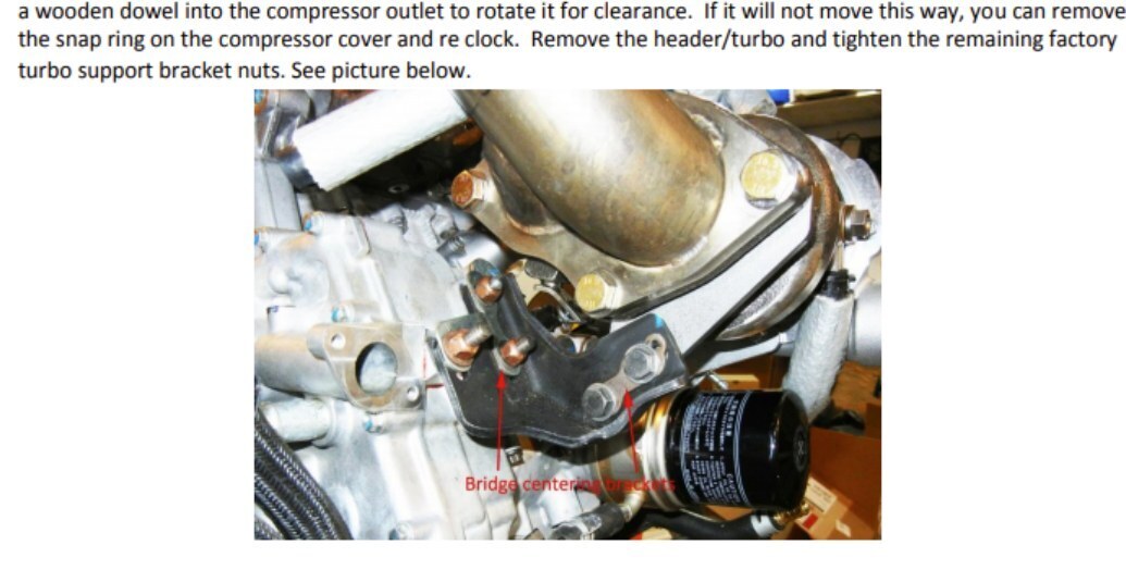
- With the header removed, rest the turbo/up-pipe in the chassis in its approximate location. Test-fit the header onto the turbo, tighten the header onto the engine, and align the supplied support bracket by moving the factory bracket up or down on its slotted holes. Verify clearance between the support bracket and the SC outlet flange. Once verified and the holes are aligned, install the bridge centering bracket and tighten the most accessible turbo support bracket nut. If clearance is tight, rotate the compressor cover by inserting a wooden dowel into the outlet to rotate it. Remove the header/turbo and tighten the remaining support-bracket nuts.
- Use the supplied M8 black bolts and thick washers for the header-to-turbo flange.
- Thread both the factory turbo support bracket and the EVP support bracket using the supplied 8 mm × 1.25 × 30 mm bolts and washers. Reuse the factory nuts and bridge centering bracket; take up the space between the two brackets with the supplied stainless-steel spacer washers. When all brackets are tightened they should not put any torque on the turbo/header/engine.
- Connect the oil-drain line to the factory drain line (the ½" line from the bottom of the engine). Reuse the factory constant-tension clamp.
- Install the EVP-supplied water banjo all the way into the free end of the molded rubber hose from step 5. Use a constant-tension clamp to secure the hose onto the barb.
- Install a supplied copper washer on each side of the banjo and slide the banjo bolt through the washers and banjo.
- Install the remaining banjo by placing a supplied copper washer on each side of the banjo and sliding the banjo bolt through the washers and banjo. Orient the banjo so the barb faces up and away from the flange of the exhaust header. Insert the banjo bolt into the threaded rear water outlet of the SC turbo and tighten to 10 ft-lb. Do not cross-thread. Insert the short end of the remaining water line onto the banjo barb; slide the fire sleeve so it completely covers the water line and the constant-tension clamp on the banjo. Refer to the picture in step 9.
- Connect the free end of the water line installed in the previous step to the coolant overflow tank. You will need to spray brake cleaner into the end of the hose to slide it onto the factory coolant tank barb. Reuse the factory constant-tension clamp. Refer to the picture in step 9.
- Install the free end of the new oil line onto the oil-restrictor fitting on top of the turbo. Slide the fire sleeve so it completely covers the fitting where it bolts onto the turbo.
- Reinstall the vacuum line from the boost-control solenoid onto the ¼" barbed turbo outlet port. Reuse the factory constant-tension clamp.
- Reassemble the heat shields and chassis braces. If you are using the EVP header/turbo/up-pipe blankets, install them now.
- Reinstall the intercooler and remaining vacuum lines.
Fuel Pump Installation — 100-Octane Kits Only
- FIRE HAZARD: it is best to do this job with the tank empty to minimize fire risk. Keep a fire extinguisher handy.
- Remove the cover that covers the fuel tank — two torx screws on the top side and a ring around the fuel filler neck must be removed to remove the cover.
- The fuel pump is in the fuel tank, accessed on the top of the fuel tank on the right side in a 4" circular access cover. Disconnect the fuel-line fitting (it connects to the access cover) by pulling up on the connector that mates with the two wires; you can also do this with needle-nose pliers or circlip pliers to expand the plastic retainer. Remove the six torx screws and remove the fuel-pump/pickup assembly.
- Take a picture of the orientation of the lines and pickup to aid in reassembly.
- Cut the clamp holding the fuel line to the bottom of the fuel pump and discard. Cut the wire tie holding the fuel line to the bracket and set the fuel line and pickups aside.
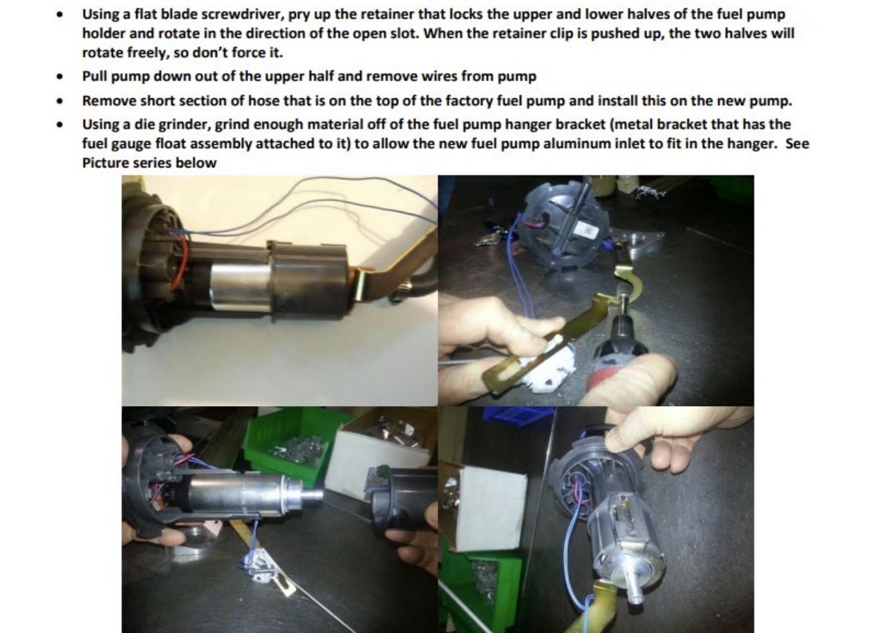
- With a flat-blade screwdriver, pry up the retainer that locks the upper and lower halves of the fuel-pump holder and rotate in the direction of the open slot; when the retainer clip is pushed up, the two halves rotate freely — do not force it.
- Pull the pump down off the upper half and remove the wires from the pump.
- Remove the short section of hose on the top of the factory pump and install it on the new pump.
- With a die grinder, grind enough material off the fuel-pump hanger bracket (the metal bracket holding the fuel-gauge float assembly) to allow the new aluminum inlet to fit in the hanger (see photo series).
- Install the new plug for the fuel pump — these wires should be soldered and shrink-wrapped — and plug it into the top of the pump.
- Reassemble the pump-holder halves and reconnect the fuel line and pickup assembly using the supplied clamp on the hose barb at the bottom of the fuel pump.
- Install a new zip tie on the fuel line as it was before.
- Reinstall the pump assembly into the tank (tricky — it is correctly installed when you can rest everything and there is no resistance when you rest the access cover onto the tank). Reinstall the six torx screws and reconnect the electric connector.
- Switch the key to 'on' and turn the kill switch 'off' — you should hear the fuel pump for about 2 seconds, then it shuts off. If you do not hear the pump, fix the problem before continuing. Switch the key 'off'.
- Take the fuel-return line out of the top left side of the tank, cut the clamp securing it to the plastic elbow, and remove the fuel line and rubber grommet from the plastic elbow.
- Place the elbow in a vise with the larger end facing up. Using an 11/64 drill bit, mark 26 mm down from the point of the drill and drill the plastic elbow from the top of the larger opening exactly to your line on the drill bit (26 mm). DO NOT DRILL TOO FAR or you will ruin the elbow — the purpose is to drill out the restrictor in the elbow to accommodate the larger fuel pump. Reinstall the elbow into the return line. Secure with the supplied clamp and reinstall the rubber grommet. Reinstall in the fuel tank.
Final Assembly & Coolant
- Add 50/50 coolant to the overflow tank until full — leave the cap off the tank for now.
- Do not install the side panels at this time.
- Install the EVP reflashed ECU.
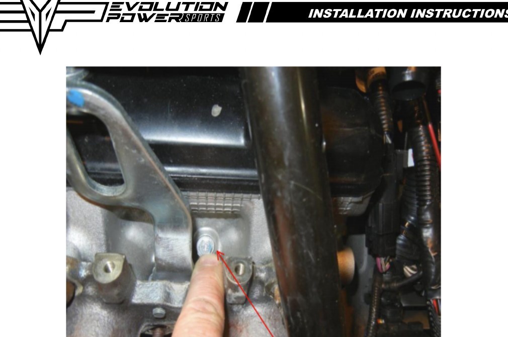
- Raise the front of the sled so the engine bleed screw (see photo) is higher than the rear heat exchanger.
- Start the engine for 15 seconds and shut off — check for leaks. If no leaks are detected, proceed to the next step.
- Add more 50/50 coolant to the overflow tank and replace the tank cap.
- Start the engine. Crack the bleed screw a small amount and feel for air coming out; let the motor idle until you can feel the rear heat exchanger getting hot. Tighten the coolant bleed screw and shut the motor off (see photo).
- Let the engine completely cool down, then refill the coolant tank to the top.
- Start the engine again and verify the rear heat exchanger gets hot after idling for 5-7 minutes.
- Install the hood and side panels and all other items removed and/or loosened.
Initial Ride
- Fuel requirements are crucial. If you have a pump-gas kit, good 93-octane non-oxygenated pump gas is REQUIRED. If only 91 is available, mix 2.5 gallons of 100LL aviation fuel per tankful. If running a race-gas kit, the octane required is 100 (standard 100LL aviation fuel).
- If you have a Sno Pro with the deluxe gauge, you can monitor coolant temperature by switching the key on and the kill switch off so the display illuminates. Push and hold the two left-hand buttons for 10 seconds; you will see the voltage on the bottom of the screen. Push the upper button until you see a '3'; to the right of the '3', the water temperature is displayed. Monitor this as you ride. If snow conditions are decent, it should never exceed 200 °F; if it does, the cooling system is airlocked — do NOT ride the sled. Re-bleed the system. If temperature stays constant and below 195, proceed riding. Check periodically for leaks.
- If you do not have a Sno Pro, periodically check the rear heat exchanger; it should be very warm to the touch. Monitor the gauges for the temperature light to come on. Once you have ridden a few miles with no codes, stop and check for leaks. If no leaks are detected, proceed.
- It is assumed that your sled has a mechanical boost gauge and an AFR gauge. These instruments are necessary for high-performance aftermarket modifications and help diagnose problems if you have any.
Note: This product is exempt from the emission standards and related requirements of 40 C.F.R. § 1051 as provided by 40 C.F.R. § 1051.620, and California law, and is sold only for use on EPA-certified, purpose-built nonroad competition/racing vehicles used solely for closed-course competition and not on public highways.