Installation instructions for the Evolution Powersports water-to-air intercooler on the Arctic Cat Proclimb/Procross 1100T/9000. Covers mounting the heat exchanger, routing silicone and hard coolant lines, and bleeding the cooling system.
ARCTIC CAT Proclimb/Procross 1100T/9000 WATER TO AIR INTERCOOLER INSTALLATION INSTRUCTIONS
TOOLS NEEDED: AWL, 1/8" & 5/16" DRILL BITS, 1-1/4" HOLE SAW, HAMMER, DUCT TAPE, AIR GRINDER OR DREMEL, SCREW DRIVER, DRILL, 50/50 ANTIFREEZE, SHARP BOX CUTTER, SCISSORS, METRIC SOCKET AND WRENCH SET.
- REMOVE LEFT & RIGHT SIDE PANELS AND HOOD
- REMOVE THE SILENCER AND DOWNPIPE FROM THE TURBO
- DRAIN COOLANT FROM TANK BY REMOVING THE HOSE ON THE BOTTOM OF THE COOLANT TANK
- USING DUCT TAPE, TAPE THE PROVIDED TEMPLATE ONTO THE LEFT SIDE OF THE FRAME BY THE SHOCK TOWER. (SEE PICTURES ON THE NEXT PAGE)
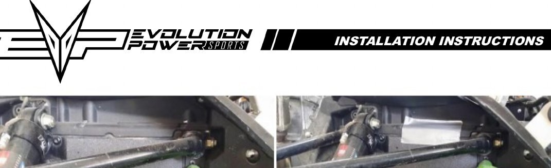
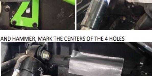
- USING AN AWL AND HAMMER, MARK THE CENTERS OF THE 4 HOLES
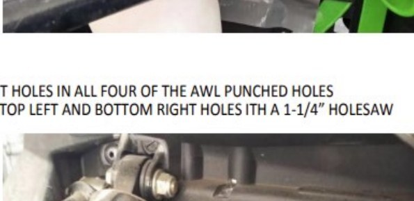
- DRILL 1/8" PILOT HOLES IN ALL FOUR OF THE AWL PUNCHED HOLES
- DRILL OUT THE TOP LEFT AND BOTTOM RIGHT HOLES ITH A 1-1/4" HOLESAW
- DRILL THE TOP RIGHT AND BOTTOM LEFT HOLES OUT WITH A 5/16" DRILL BIT
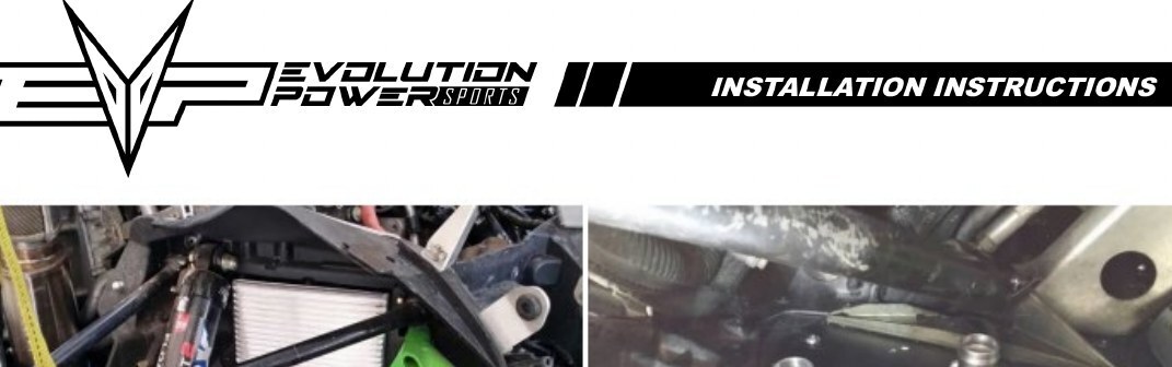
- INSTALL THE HEAT EXCHANGER. LINE UP THE THREADED BOSSES ON THE HEAT EXCHANGER WITH THE 5/16" HOLES YOU JUST DRILLED. INSTALL THE SUPPLIED BOLTS TO FASTEN THE HEAT EXCHANGER TO THE FRAME. SEE PICTURES ON NEXT PAGE
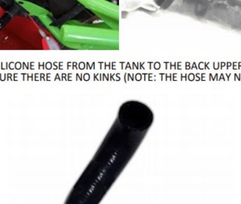
- INSTALL THE BELOW SILICONE HOSE FROM THE TANK TO THE BACK UPPER HOSE BARB ON THE HEAT EXCHANGER – MAKE SURE THERE ARE NO KINKS (NOTE: THE HOSE MAY NEED TO BE TRIMMED SLIGHTLY)
- INSTALL THE SMALL 1" DIAMETER ELBOW ONTO THE LOWER HOSE BARB OF THE HEAT EXCHANGER (NOTE: THE HOSE MAY HAVE TO BE TRIMMED SLIGHTLY TO BRING IT CLOSER TO THE FRAME AND AWAY FROM THE EXHAUST AND TURBO – DO NOT TRIM THE HEIGHT). USE THE SUPPLIED HOSE CLAMPS TO SECURE THE HOSES.
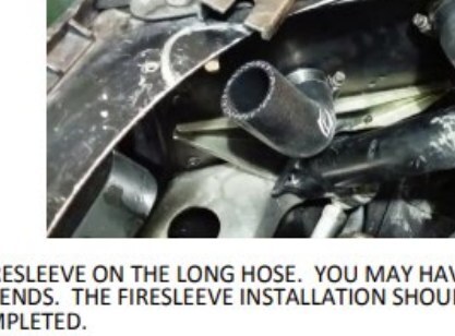
- INSTALL FIRESLEEVE ON THE LONG HOSE. YOU MAY HAVE TO INCH IT ON TO GET THE FIRESLEEVE TO SLIDE PAST THE BENDS. THE FIRESLEEVE INSTALLATION SHOULD LOOK LIKE THE PICTURE ON THE NEXT PAGE WHEN COMPLETED.
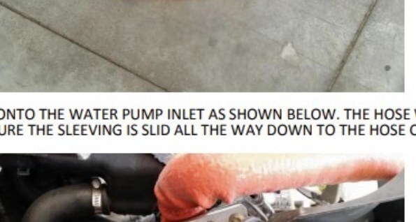
- INSTALL THE HOSE ONTO THE WATER PUMP INLET AS SHOWN BELOW. THE HOSE WILL CONTACT THE FRAME, SO MAKE SURE THE SLEEVING IS SLID ALL THE WAY DOWN TO THE HOSE CLAMP TO PROTECT IT.
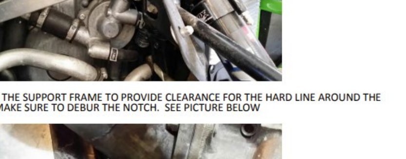
- NOTCH THE TOP OF THE SUPPORT FRAME TO PROVIDE CLEARANCE FOR THE HARD LINE AROUND THE TURBO/EXHAUST. MAKE SURE TO DEBUR THE NOTCH. SEE PICTURE BELOW
- INSTALL A SHORT PIECE OF FIRESLEEVING ONTO THE ELBOW. THEN SLIDE A CLAMP ONTO THE SILICONE ELBOW. MEASURE OUT FIRE SLEEVING TO GO OVER THE ALUMINUM HARD PIPE DOWN TO THE SILICONE ELBOW. INSERT THE ALUMINUM PIPE INTO THE ELBOW AND TIGHTEN CLAMP.
- INSTALL ADEL CLAMP ONTO THE HARD LINE AND DRILL A HOLE IN THE FRAME TO SECURE IT. YOU MAY HAVE TO INSTALL WASHERS UNDER THE BOLT TO RAISE THE ADEL CLAMP UP TO KEEP THE HARD LINE ELEVATED AND OFF OF THE FRAME. MAKESURE THERE IS CLEARANCE ALL AROUND THE HOSES AND THE SLEEVING ADEQUATELY COVERS THE SILICONE WATER LINES. SEE PICTURE ON NEXT PAGE.
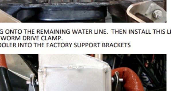
- INSTALL FIRESLEEVING ONTO THE REMAINING WATER LINE. THEN INSTALL THIS LINE ONTO THE HARD LINE AND SECURE WITH A WORM DRIVE CLAMP.
- INSTALL THE INTERCOOLER INTO THE FACTORY SUPPORT BRACKETS.
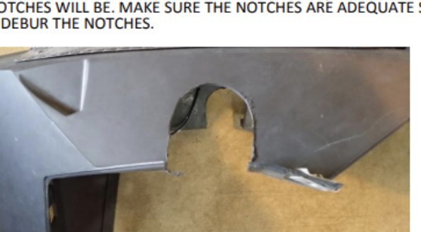
- IF YOU ARE RUNNING YOUR FACTORY HOOD, YOU WILL NEED TO NOTCH THE SHELL AS SHOWN IN THE NEXT PICTURE. IF YOUR HOOD CORRECTLY IN THE BACK AND USE THE IN/OUT INTERCOOLER WATER LINES TO MARK WHERE THE NOTCHES WILL BE. MAKE SURE THE NOTCHES ARE ADEQUATE SO THE HOOD WILL NOT RUB ON THE HOSES. DEBUR THE NOTCHES.
- FILL THE COOLING SYSTEM WITH 50/50 ANTIFREEZE.
- BECAUSE OF THE LOCATION OF THE INTERCOOLER, IT IS A LITTLE MORE DIFFICULT TO BLEED THE COOLING SYSTEM. THIS STEP REQUIRES EXTRA CAUTION AS YOU CAN BE BURNED BY HOT COOLANT!! – BE CAREFUL!!! SET THE HOOD ONTO THE SLED SO THE MAIN HARNESS CAN BE PLUGGED IN. START THE SLED AND ALLOW IT TO IDLE. USING A LONG FUNNEL, CONTINUE TO AD 50/50 COOLANT AS THE LEVEL DROPS AND THE COOLING SYSTEM IS FILLED. THE THERMOSTAT NEEDS TO OPEN TO COMPLETELY FILL THE COOLING SYSTEM. IT OPENS AT 165 DEG F. YOU CAN MONITOR THE TEMPERATURE ON THE DASH OF SNOW PRO VEHICLES BY PUSHING THE TOP AND BOTTOM LEFT BUTTONS IN AND HOLDING THEM FOR 10 SECONDS. THIS WILL CHANGE YOUR MILES TO VOLTS. USING THE TOP BUTTON, SCROLL TO THE 3RD
- SELECTION WHICH WILL BE WATER TEMPERATURE. ONCE YOU ARE SURE THAT THE SYTEM IS NOT TAKING ANY MORE COOLANT, SHUT THE MACHINE OFF. WHEN THE MACHINE HAS COMPLETELY COOLED, FILL THE COOLANT TANK TO THE TOP AND REPLACE CAP.
- LOOSEN, BUT DO NOT REMOVE THE BLEED SCREW ON THE FRONT OF THE ENGINE. IT REQUIRES AN 8MM SOCKET. SEE PICTURE BELOW
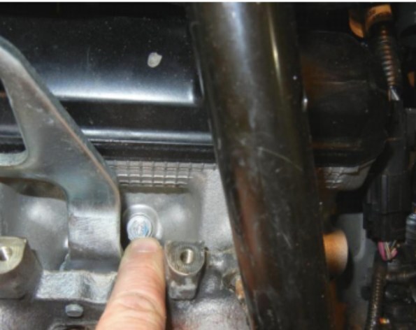
- START THE ENGINE. A SMALL VERY SMALL AMOUNT OF ANTIFREEZE SHOULD BE SEEN COMING OUT FROM BEHIND THE SCREW. LET THE MOTOR IDLE UNTIL YOU CAN FEEL BOTH SIDES OF THE REAR HEAT EXCHANGER GETTING HOT. TIGHTEN THE COOLANT BLEED SCREW ON THE ENGINE AND SHUT THE MOTOR OFF.
- LET THE MACHINE COMPLETELY COOL AGAIN. CHECK ANTIFREEZE LEVEL AND ADD IF NECESSARY.
- REINSTALL THE HOOD AND ALL PANELS. THE HOOD IS A LITTLE DIFFICULT TO INSTALL BECAUSE THE HOSES WILL FIT BETWEEN THE OUTER SHINY PLASTIC PANELS AND THE INNER SHELL WHICH YOU NOTCHED. PRY THE SIDES OF THE SHINY PANELS OPEN AS YOU SLIDE THE HOOD OVER. VERIFY CLEARANCE.
- GRIND THE POINT OFF OF THE HOOD HOLD DOWN SCREWS THAT GO INTO THE SHOCK TOWER AREA OF THE BODYWORK – THESE SHOULD NOT INTERFERE WITH THE INTERCOOLER WATER LINES, HOWEVER IT IS BETTER TO BE SAFE THAN SORRY.
FIRST RIDE
- IF YOU HAVE A SNO PRO WITH THE DELUXE GAUGE, YOU CAN MONITOR COOLANT TEMPERATURES BY SWITCHING THE KEY ON AND KILL SW OFF SO THE DISPLAY IS ILLUMINATED. PUSH IN AND HOLD THE TWO LEFT HAND BUTTONS FOR 10 SECONDS. YOU WILL SEE THE VOLTAGE APPEAR ON THE BOTTOM OF THE SCREEN. PUSH THE UPPER BUTTON UNTIL YOU SEE A "3" ON THE BOTTOM LEFT. JUST TO THE RIGHT OF THE "3", THE WATER TEMPERATURE WILL BE DISPLAYED. MONITOR THIS AS YOU RIDE. IF THE SNOW CONDITIONS ARE DECENT, IT SHOULD NEVER EXCEED 200 DEG F. IF IT DOES, THE COOLING SYSTEM IS AIRLOCKED. DO NOT RIDE THE SNOWMOBILE!!! RE BLEED THE SYSTEM. IF TEMPERATURE REMAINS CONSTANT AND AROUND 175 DEGREES, PROCEED RIDING. CHECK PERIODICALLY FOR LEAKS.
- IF YOU DO NOT HAVE A SNOW PRO, PERIODICALLY CHECK THE REAR HEAT EXCHANGER. IT SHOULD BE VERY WARM TO THE TOUCH. MONITOR THE GAUGES FOR THE TEMPERATURE LIGHT TO COME ON. ONCE YOU HAVE RIDDEN A FEW MILES WITH NO CODES, STOP AND CHECK FOR LEAKS. IF NO LEAKS ARE DETECTED, PROCEED.
Thank you for choosing Evolution Powersports products. If you require further assistance, please call our Tech Support @ (715) 247-3862.
Note: This product is exempt from the emission standards and related requirements of 40 C.F.R. § 1051 as provided by 40 C.F.R. § 1051.620, and California law [e.g., vehicle code§§ 27156 and 38391]. This product is sold only for use in connection with EPA certified, purpose-built, nonroad vehicles used solely for closed course, nonroad competition/racing and not used for any recreational purpose or on public highways or right of ways maintained by and open to the public. This product is sold only in connection with machines that do not fall under state and/or federal noise or emission standards/regulations. Purchasers who/that purchase this product represent and warrant that the product is purchased only in connection with EPA -certified, emission-regulations-exempt and noise-regulations-exempt competition/racing vehicles as interpreted under applicable state and/or federal law. Questions: Call Evolution Powersports at (715) 247-3862.