Wilwood UTV6 Front Brake Kit assembly instructions for the 2017-2023 Can-Am Maverick X3, covering the 11.25" diameter Dynamic Mount Lug-Drive Non-Vented Rotor kit (base part number 140-16628) and the UTV6 Front Race Brake Kit version (base part number 140-17040). Disc brakes should only be installed by someone experienced and competent in the installation and maintenance of disc brakes.
WarningDISC BRAKES SHOULD ONLY BE INSTALLED BY SOMEONE EXPERIENCED AND COMPETENT IN THE INSTALLATION AND MAINTENANCE OF DISC BRAKES. READ ALL WARNINGS.
What's in the Box
WarningWARNING: It is the responsibility of the person installing any brake component or kit to determine the suitability of the component or kit for that particular application. If you are not sure how to safely use this brake component or kit, you should not install or use it. Do not assume anything. Improperly installed or maintained brakes are dangerous. If you are not sure, get help or return the product.
WarningRacing equipment and brakes must be maintained and should be checked regularly for fatigue, damage, and wear.
WarningWARNING: DO NOT OPERATE ANY VEHICLE ON UNTESTED BRAKES! SEE MINIMUM TEST PROCEDURE WITHIN. Always utilize safety restraint systems and all other available safety equipment while operating the vehicle.
ImportantIMPORTANT - READ THE DISCLAIMER OF WARRANTY INCLUDED IN THE KIT.
NoteNOTE: Some cleaners may stain or remove the finish on brake system components. Test the cleaner on a hidden portion of the component before general use.
ImportantImportant Notice - Read This First: Wilwood Disc Brake components and complete brake kits are designed for factory, un-modified vehicles, as a direct bolt-on system with little or no alterations to be made to factory component designs. When adding aftermarket components such as hubs, spindles/uprights, suspension, brake lines and wheels, fitment of the Wilwood components must be verified by the installer through the full range articulation of the suspension. Failure to do so may result in damage to the vehicle and/or the Wilwood Disc Brake kit.
ImportantImportant: Before assembling this kit, see "Modification Instructions" on page 4 for information on clearancing the upright for proper caliper mounting.
WarningDue to OEM production differences and other variations from vehicle to vehicle, the fastener hardware and other components in this kit may not be suitable for a specific application or vehicle.
WarningIt is the responsibility of the purchaser and installer of this kit to verify suitability / fitment of all components and ensure all fasteners and hardware achieve complete and proper engagement. Improper or inadequate engagement can lead to component failure.
WarningSTEP 8 CAUTION: The caliper in this brake kit utilizes a 10mm x 1.25 thread inlet, the same as the Original Equipment Manufacturer (OEM) caliper.
WarningSTEP 8 CAUTION: In absence of specific instructions for brake line routing, the installer must use best professional judgment on correct routing and retention of lines to ensure safe operation. It is the installer's responsibility to properly route and provide adequate clearance and retention for brake hose components.
WarningSTEP 8: Do not use lubricant or thread sealant on banjo bolt (13). Torque to minimum value shown in Figure 1. Check for leakage, increasing torque only to stop leakage without exceeding maximum specification. Replace crush washers and banjo bolt whenever reassembly is required. Ensure hoses are routed to prevent contact with moving suspension, brake or wheel components.
WarningSTEP 9 CAUTION: Test vehicle brake system per the Minimum Test Procedure stated within this document before driving. After road testing, inspect for leaks and interference. Initially after install and testing, perform frequent checks of the vehicle brake system and lines before driving, to confirm that there is no undue wear or interference not apparent from the initial test. Afterwards, perform periodic inspections for function, leaks and wear in a interval relative to the usage of vehicle.
WarningIt is also the installer's responsibility to ensure that all fittings and hoses are the correct size and length, properly seat, and that they will not be subject to crimping, strain and abrasion from vibration or interference with suspension components, brake rotor or wheel.
NoteNOTE: A MINIMUM OF .090" CLEARANCE MUST BE MAINTAINED BETWEEN THE WHEEL AND CALIPER IN ALL AREAS.
WarningWARNING - DO NOT DRIVE ON UNTESTED BRAKES. BRAKES MUST BE TESTED AFTER INSTALLATION OR MAINTENANCE. MINIMUM TEST PROCEDURE.
WarningAlways wear seat belts and make use of all safety equipment.
NoteNOTE: NEVER allow the contact surfaces of the pads or rotors to be contaminated with brake fluid. Always use a catch bottle with a hose to prevent fluid spill during all brake bleeding procedures.
Diagrams & Reference
Torque Specifications
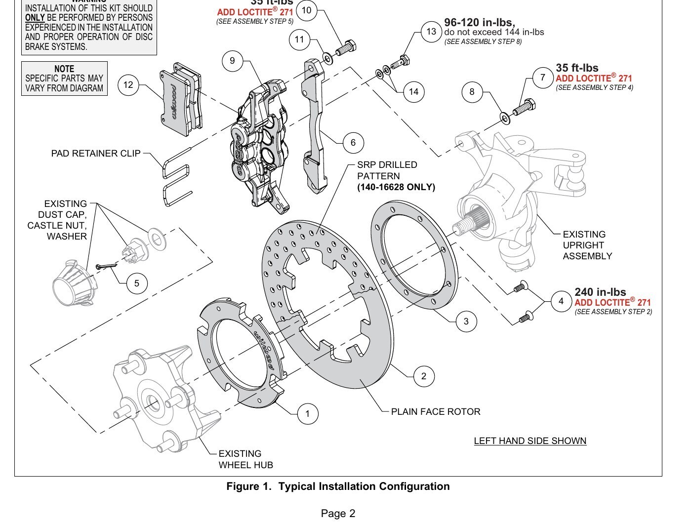
- Bolts (4) M8 rotor adapter bolts: 240 in-lbs, ADD LOCTITE 271 (see Assembly Step 2 / Figure 1)
- Bolts (7) M10 caliper mounting bracket bolts: 35 ft-lbs, ADD LOCTITE 271 (see Assembly Step 4 / Figure 1)
- Bolts (10) M10 caliper-to-bracket bolts: 35 ft-lbs, ADD LOCTITE 271 (see Assembly Step 5 / Figure 1)
- Banjo bolt (13): 96-120 in-lbs, do not exceed 144 in-lbs (see Assembly Step 8 / Figure 1)
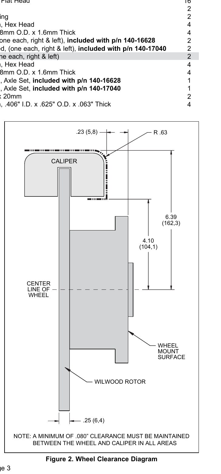
- Wheel-to-caliper clearance: minimum of .090" must be maintained between the wheel and caliper in all areas (Figure 2)
- Caliper brake line inlet thread: 10mm x 1.25 (same as OEM)
- Banjo bolt thread: M10-1.25 x 20mm
- Rotor: .25" Thk x 11.25" Diameter, Dynamic Mount, 8-Lug
- Rotor adapter bolt circle: 4 x 6.30"
- Caliper dimensions (Figure 2): 6.39" (162.3mm) overall height reference, 4.10" (104.1mm) reference, .63" radius reference, 23" (5.8) reference, 25mm (6.4) wheel mount surface reference
- Brake fluid options: Wilwood Hi-Temp 570, EXP 600 Plus, or XR Race-Only Brake Fluid. For extreme braking temperatures (endurance racing), use Wilwood XR Race-Only Brake Fluid (not DOT approved, off-highway use only). Used fluid must be completely flushed from the system before refilling. NOTE: Wilwood DOT 5 brake fluid is NOT recommended for racing or performance driving.
- Bedding hard deceleration range: 8-10 decelerations from 55-65 MPH down to 25 MPH
- Dyno-bedded pads and rotors run-in: Spec 37 GT series rotors
Installation
- Disassembly Instructions - Disassemble the original equipment front brakes. Raise the front wheels off the ground and support the front suspension according to the vehicle manufacturer's instructions. Remove the front wheels, calipers, wheel hubs, and rotors. Remove any nicks or burrs on the wheel hub and upright that may interfere with the installation of the new brake components. Clean and de-grease the wheel hub, and upright.
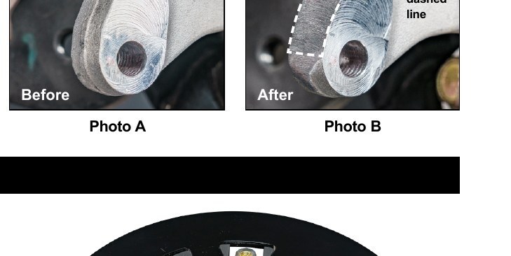
- Modification Instructions - NOTE: Some grinding of the casting line on the outer edge of lower caliper mounting tab of upright may be required for proper fitment of new caliper. If necessary, only grind off enough material to provide adequate clearance so that the Wilwood caliper does not touch the mounting tab and properly attaches to caliper mounting bracket without any binding, see Photos A and B at right.
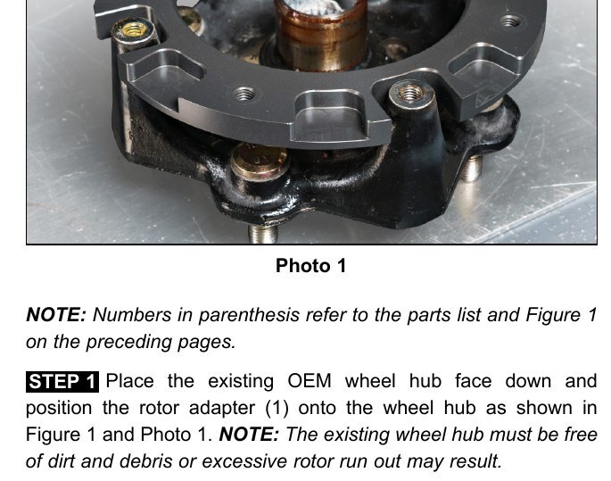
- Place the existing OEM wheel hub face down and position the rotor adapter (1) onto the wheel hub as shown in Figure 1 and Photo 1. NOTE: The existing wheel hub must be free of dirt and debris or excessive rotor run out may result.
- Position the rotor (2) onto the rotor adapter (1), making sure the rotor lugs fit into the recesses of the rotor adapter, as shown in Photo 2. Place the adapter ring (3) onto the assembly and attach using bolts (4), Photos 3 and 4. Using an alternating sequence, apply red Loctite 271 to the threads of the bolts (4) and torque to value shown in Figure 1.
- Grease the splines and outer snout of the existing wheel hub and slide the wheel hub/rotor assembly onto the axle and attach using the existing OEM washer and castle nut. Tighten to OEM specifications and secure using cotter pin (5), Photo 5. Reinstall the existing dust cap, Photo 6.
- Orient the caliper mounting bracket (6), as shown in Figure 1 and Photo 7. Install using bolts (7) and washers (8). Apply red Loctite 271 to the bolt threads and torque to value shown in Figure 1.
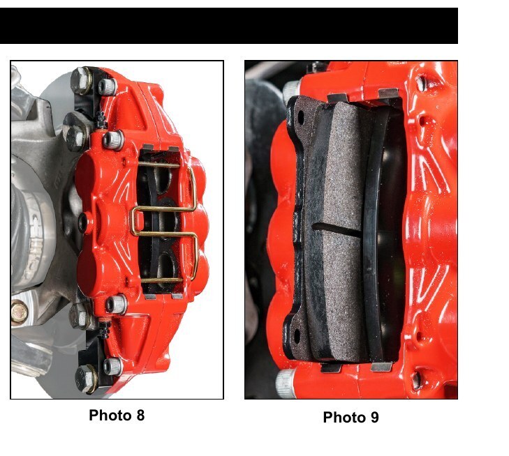
- Secure the caliper (9) to the mounting bracket (6) using bolts (10) and washers (11), as shown in Figure 1 and Photo 8. Apply red Loctite 271 to the threads and torque to value shown in Figure 1.
- Remove the pad retainer clip from the caliper (9). Insert the brake pads into the caliper with the friction material facing the rotor, as shown in Photo 9. Reinstall the pad retainer clip, Photo 10.
- Temporarily install the wheel and torque the lug nuts to the manufacturer's specification. Ensure that the wheel rotates freely without any interference. Remove wheel for next step.
- Attach brake line to caliper. Orient OEM brake line as shown in Photo 11 and connect to caliper using banjo bolt (13) and crush washers (14). Do not use lubricant or thread sealant on banjo bolt (13). Torque to minimum value shown in Figure 1. Check for leakage, increasing torque only to stop leakage without exceeding maximum specification. Replace crush washers and banjo bolt whenever reassembly is required. Ensure hoses are routed to prevent contact with moving suspension, brake or wheel components. The caliper in this brake kit utilizes a 10mm x 1.25 thread inlet, the same as the Original Equipment Manufacturer (OEM) caliper. CAUTION: In absence of specific instructions for brake line routing, the installer must use best professional judgment on correct routing and retention of lines to ensure safe operation. It is the installer's responsibility to properly route and provide adequate clearance and retention for brake hose components. It is also the installer's responsibility to ensure that all fittings and hoses are the correct size and length, properly seat, and that they will not be subject to crimping, strain and abrasion from vibration or interference with suspension components, brake rotor or wheel.
- Bleed the brake system, referring to the Additional Information and Recommendations on page 6 for proper bleeding instructions. Check system for leaks after bleeding. CAUTION: Test vehicle brake system per the Minimum Test Procedure stated within this document before driving. After road testing, inspect for leaks and interference. Initially after install and testing, perform frequent checks of the vehicle brake system and lines before driving, to confirm that there is no undue wear or interference not apparent from the initial test. Afterwards, perform periodic inspections for function, leaks and wear.
- Install the wheel and torque the lug nuts to manufacturer's specifications.
- Bed-in the brake pads for the procedure on page 7 (Pad and Rotor Bedding). Begin with a series of light decelerations to gradually build some heat in the brakes. Use an on-and-off the pedal technique by applying the brakes for 3-5 seconds, and then allow them to fully release for a period roughly twice as long as the deceleration cycle. If you use a 5 count during the deceleration interval, use a 10 count during the release to allow the heat to sink into the pads and rotors. After several cycles of light stops to begin warming the brakes, proceed with a series of medium to firm deceleration stops to continue raising the temperature level in the brakes. Finish the bedding cycle with a series of 8-10 hard decelerations from 55-65 MPH down to 25 MPH while allowing a proportionate release and heat-sinking interval between each stop. The pads should now be providing positive and consistent response. If any amount of brake fade is observed during the bed-in cycle, immediately begin the cool down cycle. Drive at a moderate cruising speed, with the least amount of brake contact possible, until most of the heat has dissipated from the brakes. Avoid sitting stopped with the brake pedal depressed to hold the car in place during this time. Park the vehicle and allow the brakes to cool to ambient air temperature.