Assembly instructions for the Wilwood UTV4 Rear Brake Kit with 11.25" diameter dynamic mount lug-drive non-vented rotors (base part number 140-16629), or the UTV4 Rear Race Brake Kit (base part number 140-17041), for 2017-2023 Can-Am Maverick X3. Disc brakes should only be installed by someone experienced and competent in the installation and maintenance of disc brakes.
WarningREAD ALL WARNINGS.
What's in the Box
WarningWARNING: It is the responsibility of the person installing any brake component or kit to determine the suitability of the component or kit for that particular application. If you are not sure how to safely use this brake component or kit, you should not install or use it. Do not assume anything. Improperly installed or maintained brakes are dangerous. If you are not sure, get help or return the product. You may obtain additional information and technical support by calling Wilwood at (805) 388-1188, or visit our web site at www.wilwood.com. Use of Wilwood technical support does not guarantee proper installation. You, or the person who does the installation must know how to properly use this product. It is not possible over the phone to understand or foresee all the issues that might arise in your installation. Racing equipment and brakes must be maintained and should be checked regularly for fatigue, damage, and wear.
WarningWARNING: DO NOT OPERATE ANY VEHICLE ON UNTESTED BRAKES! See minimum test procedure within. Always utilize safety restraint systems and all other available safety equipment while operating the vehicle.
ImportantIMPORTANT - READ THE DISCLAIMER OF WARRANTY INCLUDED IN THE KIT.
NoteNOTE: Some cleaners may stain or remove the finish on brake system components. Test the cleaner on a hidden portion of the component before general use.
CautionCAUTION: In absence of specific instructions for brake line routing, the installer must use his best professional judgment on correct routing and retention of lines to ensure safe operation. It is the installer's responsibility to properly route and provide adequate clearance and retention for brake hose components. It is also the installer's responsibility to ensure that all fittings and hoses are the correct size and length, properly seal, and that they will not be subject to crimping, strain and abrasion from vibration or interference with suspension components, brake rotor or wheel.
CautionCAUTION: Test vehicle brake system per the 'Minimum Test Procedure' stated within this document before driving.
WarningWARNING - DO NOT DRIVE ON UNTESTED BRAKES. BRAKES MUST BE TESTED AFTER INSTALLATION OR MAINTENANCE. MINIMUM TEST PROCEDURE.
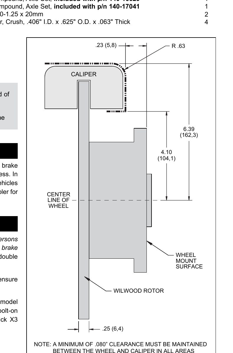
NoteNOTE: A MINIMUM OF .080" CLEARANCE MUST BE MAINTAINED BETWEEN THE WHEEL AND CALIPER IN ALL AREAS.
NoteNOTE: NEVER allow the contact surfaces of the pads or rotors to be contaminated with brake fluid. Always use a catch bottle with a hose to prevent fluid spill during all brake bleeding procedures.
Diagrams & Reference
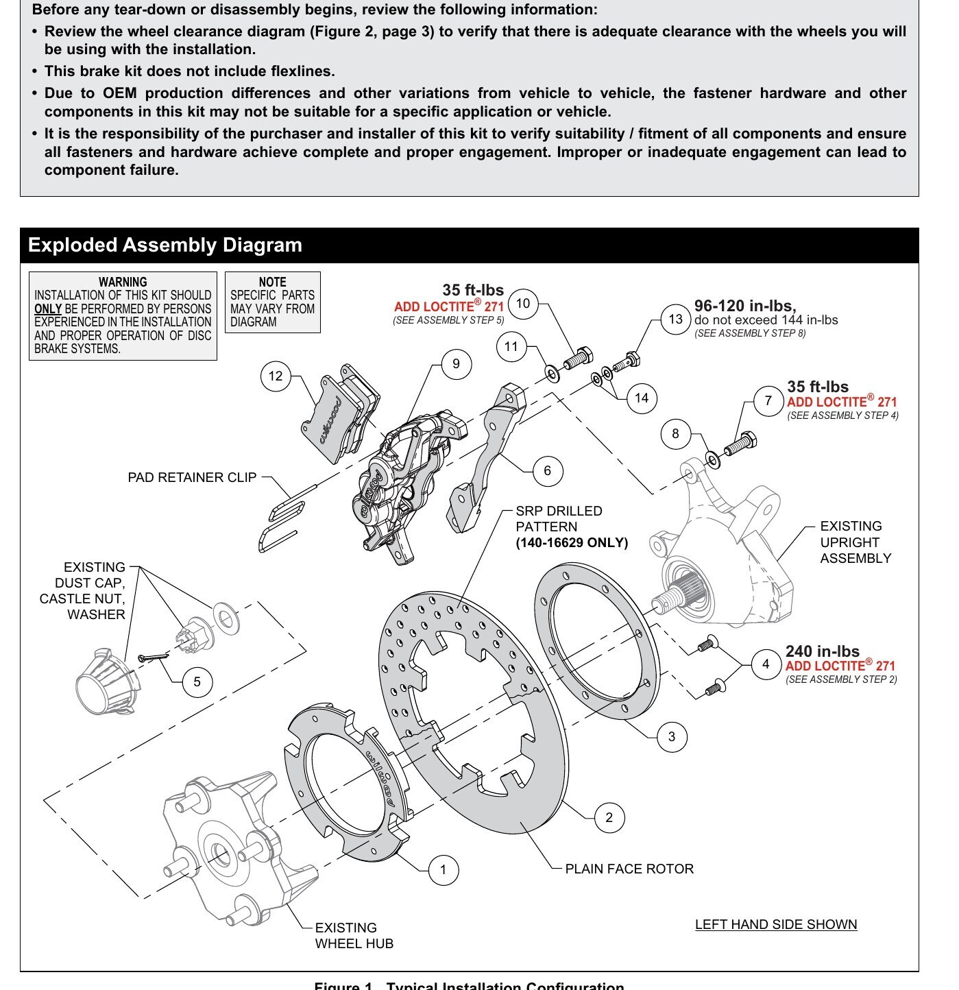
Torque Specifications
- Item 4 / Step 2 (rotor adapter ring bolts): 240 in-lbs, Add Loctite 271
- Item 7 / Step 4 (caliper mounting bracket bolts): 35 ft-lbs, Add Loctite 271
- Item 10 / Step 5 (caliper to mounting bracket bolts): 96-120 in-lbs (do not exceed 144 in-lbs), Add Loctite 271
- Item 13 (banjo bolt): 35 ft-lbs, Add Loctite 271
- Caliper-to-bracket mounting bolt callout in diagram: 35 ft-lbs, Add Loctite 271
- Brake kit utilizes a 10mm x 1.25 thread inlet, same as the OEM caliper
- Wheel clearance: minimum .080" clearance between wheel and caliper in all areas (Figure 2)
- Recommended brake fluids: Wilwood Hi-Temp 570 grade fluid, Wilwood EXP 600 Plus, or XR Race-Only fluid. For severe braking or sustained high heat operation, use Wilwood EXP 600 Plus Racing Brake Fluid; for extreme braking temperatures of endurance racing, use Wilwood XR Race-Only Brake Fluid (not DOT approved, off-highway use only). Silicone DOT 5 brake fluid is NOT recommended for racing or performance driving.
- Bedding: vary speed, with the least amount of brake contact possible, until most of the heat has dissipated from the brakes. Initial bedding at speeds up to 65 MPH; series of 8-10 hard decelerations from 55-65 MPH down to 25 MPH while allowing a proportionate release and heat-sinking interval between each stop.
- Dyno bedded competition pads and rotors: Spec 37 GT series rotors
Installation
- Disassembly Instructions: Disassemble the original equipment rear brakes. Raise the rear wheels off the ground and support the rear suspension according to the vehicle manufacturer's instructions. Remove the rear wheels, calipers, wheel hubs, and rotors. Remove any nicks or burrs on the wheel hub and upright that may interfere with the installation of the new brake components. Clean and de-grease the wheel hub, and upright.
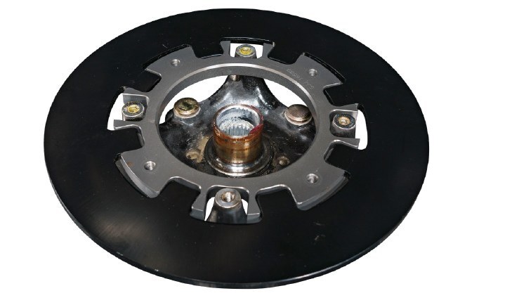
- STEP 1: Place the existing OEM wheel hub face down and position the rotor adapter (1) onto the wheel hub as shown in Figure 1 and Photo 1. NOTE: The existing wheel hub must be free of dirt and debris or excessive rotor run out may result.
- STEP 2: Position the rotor (2) onto the rotor adapter (1), making sure the rotor lugs fit into the recesses of the rotor adapter, as shown in Photo 2. Place the adapter ring (3) over the assembly and attach using bolts (4), Photos 3 and 4. Using an alternating sequence, apply red Loctite 271 to the threads, and torque to value shown in Figure 1.
- STEP 3: Grease the splines and outer snout of the existing wheel hub and slide the wheel hub/rotor assembly onto the axle and attach using the existing OEM washer and castle nut. Tighten to OEM specifications and secure using cotter pin (5), Photo 5. Reinstall the existing dust cap, Photo 6.
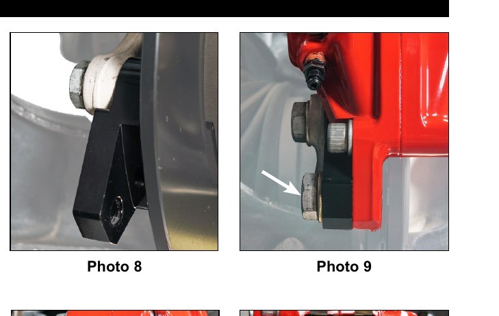
- STEP 4: Orient the caliper mounting bracket (6), as shown in Figure 1 and Photos 7 and 8. Install using bolts (7) and washers (8). Apply red Loctite 271 to the bolt threads and torque to value shown in Figure 1.
- STEP 5: Secure the caliper (9) to the mounting bracket (6) using bolts (10) and washers (11), Photo 9. Apply red Loctite 271 to the threads, and torque to value shown in Figure 1.
- STEP 6: Remove the pad retainer clip from the caliper (9). Insert the brake pads into the caliper with the friction material facing the rotor, as shown in Photo 10. Reinstall the pad retainer clip, Photo 11.
- STEP 7: Temporarily install the wheel and torque the lug nuts to the manufacturer's specification. Ensure that the wheel rotates freely without any interference. Remove wheel for next step.
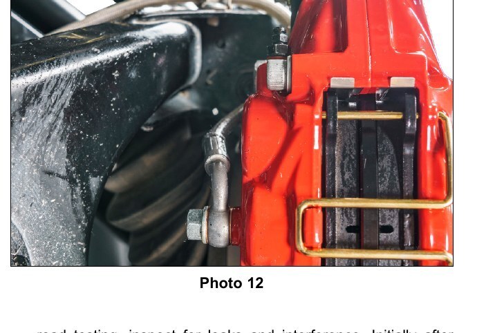
- STEP 8: Attach brake line to caliper. Orient OEM brake line as shown in Photo 12 and connect to caliper using banjo bolt (13) and crush washers (14). Do not use lubricant or thread sealant on banjo bolt (13). Torque to minimum value shown in Figure 1. Check for leakage, increasing torque only to stop leakage without exceeding maximum specification. Replace crush washers and banjo bolt whenever reassembly is required. Ensure hoses are routed to prevent contact with moving suspension, brake or wheel components. NOTE: The caliper in this brake kit utilizes a 10mm x 1.25 thread inlet, the same as the Original Equipment Manufacturer (OEM) caliper.
- STEP 9: Bleed the brake system, referring to the 'Additional Information and Recommendations' on page 6 for proper bleeding instructions. Check system for leaks after bleeding.
- STEP 10: Install the wheel and torque the lug nuts to manufacturer's specifications. CAUTION: Test vehicle brake system per the 'Minimum Test Procedure' stated within this document before driving. After road testing, inspect for leaks and interference. Initially after install and testing, perform frequent checks of the vehicle brake system and lines before driving, to confirm that there is no undue wear or interference not apparent from the initial test. Afterwards, perform periodic inspections for function, leaks and wear in a interval relative to the usage of vehicle.
- STEP 11: Bed-in the brake pads per the procedure on page 7.