Assembly and installation instructions for the Wilwood DynaPro 4R Front Brake Kit with 11.25" diameter dynamic mount, lug-drive, non-vented rotors for the 2022-2023 Polaris RZR Turbo & Pro R (5-Lug). Base Part Number 140-17568 (standard) or 140-17731 (Race).
WarningDISC BRAKES SHOULD ONLY BE INSTALLED BY SOMEONE EXPERIENCED AND COMPETENT IN THE INSTALLATION AND MAINTENANCE OF DISC BRAKES. READ ALL WARNINGS.
What's in the Box
WarningWARNING: It is the responsibility of the person installing any brake component or kit to determine the suitability of the component or kit for that particular application. If you are not sure how to safely use this brake component or kit, you should not install or use it. Do not assume anything. Improperly installed or maintained brakes are dangerous. If you are not sure, get help or return the product. You may obtain additional information and technical support by calling Wilwood at (805) 388-1188, or visit our web site at www.wilwood.com. Use of Wilwood technical support does not guarantee proper installation. You, or the person who does the installation must know how to properly use this product. It is not possible over the phone to understand or foresee all the issues that might arise in your installation.
WarningRacing equipment and brakes must be maintained and should be checked regularly for fatigue, damage, and wear.
WarningWARNING: DO NOT OPERATE ANY VEHICLE ON UNTESTED BRAKES! SEE MINIMUM TEST PROCEDURE WITHIN. Always utilize safety restraint systems and all other available safety equipment while operating the vehicle.
ImportantIMPORTANT - READ THE DISCLAIMER OF WARRANTY INCLUDED IN THE KIT.
NoteNOTE: Some cleaners may stain or remove the finish on brake system components. Test the cleaner on a hidden portion of the component before general use.
WarningWARNING: Installation of this kit should ONLY be performed by persons experienced in the installation and proper operation of disc brake systems.
WarningWARNING - DO NOT DRIVE ON UNTESTED BRAKES. BRAKES MUST BE TESTED AFTER INSTALLATION OR MAINTENANCE. MINIMUM TEST PROCEDURE: Make sure pedal is firm: Hold firm pressure on pedal for several minutes, it should remain in position without sinking. If pedal sinks toward floor, check system for fluid leaks. DO NOT drive vehicle if pedal does not stay firm or can be pushed to the floor with normal pressure. At very low speed (2-5 mph) apply brakes hard several times while turning steering from full left to full right, repeat several times. Remove the wheels and check that components are not touching, rubbing, or leaking. Carefully examine all brake components, brake lines, and fittings for leaks and interference. Make sure there is no interference with wheels or suspension components. Drive vehicle at low speed (15-20 mph) making moderate and hard stops. Brakes should feel normal and positive. Again check for leaks and interference. Always test vehicle in a safe place where there is no danger to (or from) other people or vehicles. Always wear seat belts and make use of all safety equipment.
CautionCAUTION: In absence of specific instructions for brake line routing, the installer must use his best professional judgment on correct routing and retention of lines to ensure safe operation. It is the installer's responsibility to ensure that all fittings and hoses are the correct size and length, properly seated, and that they will not be subject to crimping, strain and abrasion from vibration or interference with suspension components, brake rotor or wheel.
WarningEnsure hoses are routed to prevent contact with moving suspension, brake or wheel components.
CautionCAUTION: Test vehicle brake system per the 'Minimum Test Procedure' stated within this document before driving. After road testing, inspect for leaks and interference. Initially after install and testing, perform frequent checks of the vehicle brake system and lines before driving, to confirm that there is no undue wear or interference not apparent from the initial test. Afterwards, perform periodic inspections for function, leaks and wear in an interval relative to the usage of vehicle.
NoteNOTE: With the installation of after market disc brakes, the wheel track may change depending on the application. Check your wheel offset before final assembly.
NoteNOTE: NEVER allow the contact surfaces of the pads or rotors to be contaminated with brake fluid. Always use a catch bottle with a hose to prevent fluid spill during all brake bleeding procedures.
WarningDO NOT REUSE STOCK BANJO BOLT (regarding the 96-120 in-lbs axle set / banjo bolt callout in Figure 1).
ImportantImportant Notice - Read This First: Wilwood Disc Brake components and complete brake kits are designed for factory, un-modified vehicles, as a direct bolt-on system with little or no alterations to be made to factory component designs. When adding aftermarket components such as hubs, spindles/uprights, suspension, brake lines and wheels, fitment of the Wilwood components must be verified by the installer through the full range articulation of the suspension. Failure to do so may result in damage to the vehicle and/or the Wilwood Disc Brake kit.
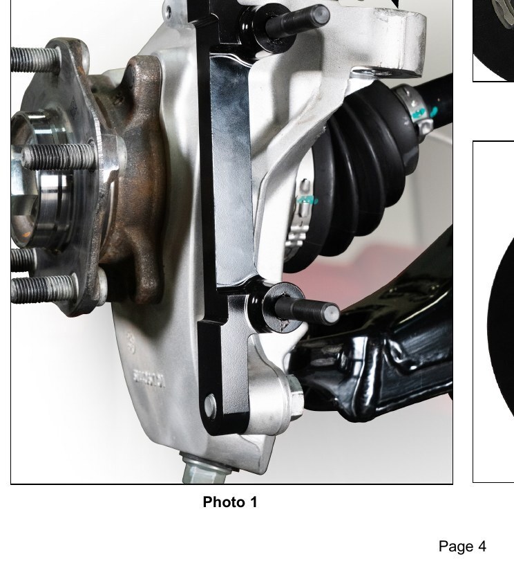
NoteNOTE: The bracket must fit squarely against the mount bosses on the upright.
NoteNOTE: The hat must fit flush against the axle hub flange or excessive rotor run out may result.
Diagrams & Reference
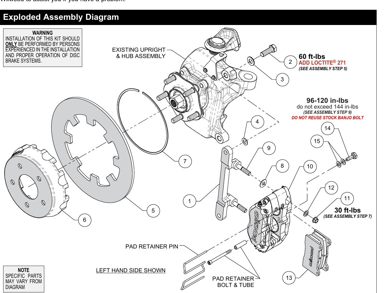
Torque Specifications
- Caliper Mounting Bolt (Item 2, Add Loctite 271): 60 ft-lbs (see Assembly Step 5)
- Banjo Bolt / Axle Set: 96-120 in-lbs, do not exceed 144 in-lbs (see Assembly Step 9) - DO NOT REUSE STOCK BANJO BOLT
- Caliper Mounting / Self-Locking Nut (Item 11): 30 ft-lbs (see Assembly Step 7)
- Caliper banjo bolt thread inlet: M10mm x 1.25mm (10mm x 1.25 thread inlet)
- OEM caliper thread inlet: M10mm x 1.00mm (10mm x 1.00)
- Caliper Mounting Bracket bolts (Step 1): use .033" thick shim (Item 4) under each bolt
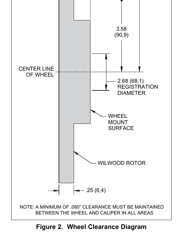
- Wheel Clearance Diagram (Figure 2): Caliper radius R 1.00" (25.4); 6.61" (167.9); 3.58" (90.9); 2.68" (68.1) Registration Diameter; .25" (6.4) wheel mount surface dimension. A minimum of .060" clearance must be maintained between the wheel and the caliper in all areas.
- Pad/Rotor bedding: build initial heat over 3-5 light decelerations from 55-65 MPH down to 25 MPH; on track from 65 MPH
- Dyno bedded competition pads and rotors: see Spec 37 GT series
Installation
- The caliper mount bracket (1) should initially be installed with clean, dry threads on the mounting bolts. Orient the bracket, as shown in Figure 1 and Photo 1, and install using bolts (2) and washers (3). Initially place one .033" thick shim (4) on each bolt between the bracket and upright, Figure 1. Temporarily tighten the mounting bolts. NOTE: The bracket must fit squarely against the mount bosses on the upright. Inspect for interference from casting irregularities, machining ridges, burrs, etc. Later, after the caliper alignment has been checked, the mount bolts will be secured using red Loctite 271. Disconnect the steering arm for removal of stock OEM caliper bolt and installation of Wilwood bracket bolt (Photo 1).
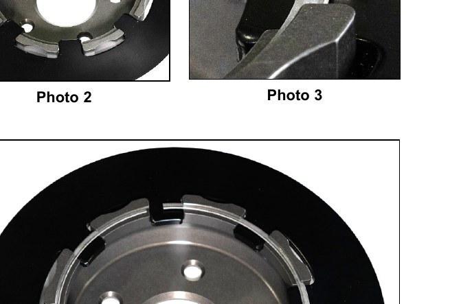
- Position the rotor (5) onto the hat (6), making sure the rotor lugs fit into the recesses of the hat, as shown in Photo 2.
- Secure rotor to the hat using the snap ring (7) by installing the ring into the groove in the hat, as shown in Photos 3 and 4. Carefully inspect snap ring to ensure complete engagement in the groove.
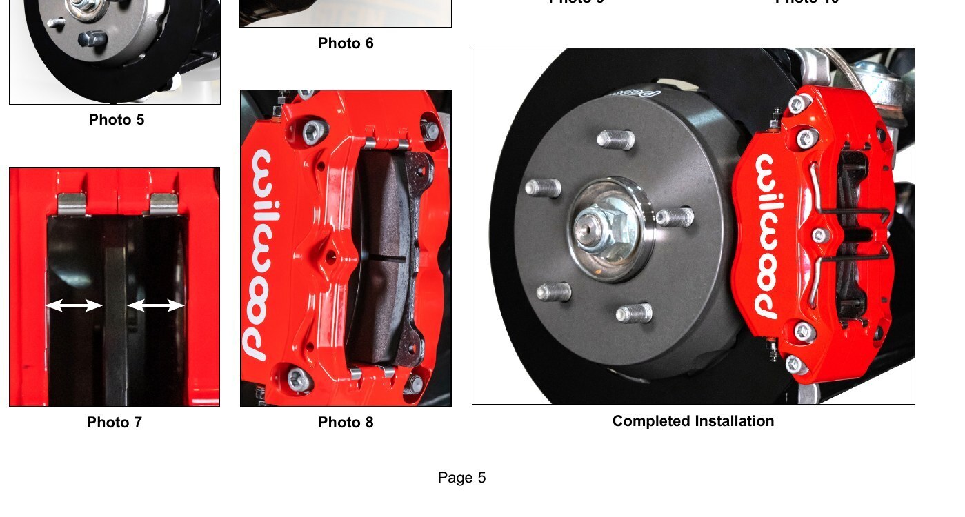
- Slide the hat/rotor assembly onto the axle hub. NOTE: The hat must fit flush against the axle hub flange or excessive rotor run out may result. Install three lug nuts to keep the hat/rotor assembly in place while continuing with the installation, Photo 5.
- Initially place one .035" thick shim (8) on each stud (9) between the caliper and the bracket (1), as shown in Figure 1 and Photo 6. Mount the caliper (10) onto the bracket (1) using lock nuts (11) and washers (12), Figure 1. Temporarily tighten the lock nuts. View the rotor through the top opening of the caliper. The rotor should be centered in the caliper, Photo 7. If not, adjust by adding or subtracting shims (4) between the bracket and the upright. Always use the same amount of shims on each of the two mounting bolts. Once the caliper alignment is correct, remove the bracket mounting bolts (2) one at a time, apply red Loctite 271 to the threads, and torque to value shown in Figure 1. Caliper mount bracket bolts (Item 2): apply red Loctite 271 and torque to 60 ft-lbs.
- Remove the pad retainer clip from the caliper (10). Insert the brake pads (13) into the caliper with the friction material facing the rotor, as shown in Photo 8.
- Check that the top of the brake pad is flush with the outside diameter of the rotor, Photo 9. If not, adjust by adding or subtracting shims (8) between the caliper and the bracket. After the caliper pad height is set, torque the caliper lock nuts (11) to value shown in Figure 1. Reinstall the pad retainer bolt, tube, and clip, Photo 10. Caliper lock nuts (Item 11): torque to 30 ft-lbs.
- Temporarily install the wheel and torque the lug nuts to the manufacturer's specification. Ensure that the wheel rotates freely without any interference. Remove wheel for next step. NOTE: The caliper in this brake kit utilizes a 10mm x 1.25 thread inlet, NOT the same as the Original Equipment Manufacturer (OEM) caliper thread inlet (10mm x 1.00). The new banjo bolt supplied with this kit must be used.
- Attach brake line to caliper. Connect OEM brake line to caliper using banjo bolt (14) and crush washers (15). Do not use lubricant or thread sealant on banjo bolt (14). Torque to minimum value shown in Figure 1. Check for leakage, increasing torque only to stop leakage without exceeding maximum specification. Replace crush washers and banjo bolt whenever reassembly is required. Ensure hoses are routed to prevent contact with moving suspension, brake or wheel components. Banjo bolt / axle set: torque 96-120 in-lbs, do not exceed 144 in-lbs. DO NOT REUSE STOCK BANJO BOLT. CAUTION: In absence of specific instructions for brake line routing, the installer must use his best professional judgment on correct routing and retention of lines to ensure safe operation. It is the installer's responsibility to ensure that all fittings and hoses are the correct size and length, properly seated, and that they will not be subject to crimping, strain and abrasion from vibration or interference with suspension components, brake rotor or wheel.
- Bleed the brake system, referring to the 'Additional Information and Recommendations' on page 6 for proper bleeding instructions. Check system for leaks after bleeding.
- Reconnect the steering arm to upright and torque to manufacturer's specifications.
- Install the wheel and torque the lug nuts to manufacturer's specifications. CAUTION: Test vehicle brake system per the 'Minimum Test Procedure' stated within this document before driving. After road testing, inspect for leaks and interference. Initially after install and testing, perform frequent checks of the vehicle brake system and lines before driving, to confirm that there is no undue wear or interference not apparent from the initial test. Afterwards, perform periodic inspections for function, leaks and wear in an interval relative to the usage of vehicle.
- Bed-in the brake pads per the procedure on page 7.