Assembly instructions (DS-1597) for the Wilwood DynaPro 4R Rear Brake Kit with 11.25" diameter dynamic mount lug-drive non-vented rotors for 2022-2023 Polaris RZR Turbo & Pro R (5-Lug). Base part numbers 140-17735 (DynaPro 4R Rear) and 140-17734 (DynaPro 4R Rear Race).
WarningDISC BRAKES SHOULD ONLY BE INSTALLED BY SOMEONE EXPERIENCED AND COMPETENT IN THE INSTALLATION AND MAINTENANCE OF DISC BRAKES. READ ALL WARNINGS.
What's in the Box
WarningWARNING: It is the responsibility of the person installing any brake component or kit to determine the suitability of the component or kit for that particular application. If you are not sure how to safely use this brake component or kit, you should not install or use it. Do not assume anything. Improperly installed or maintained brakes are dangerous. If you are not sure, get help or return the product. You may obtain additional information and technical support by calling Wilwood at (805) 388-1188, or visit our web site at www.wilwood.com. Use of Wilwood technical support does not guarantee proper installation. You, or the person who does the installation, must know how to properly use this product. It is not possible over the phone to understand or foresee all the issues that might arise in your installation.
WarningRacing equipment and brakes must be maintained and should be checked regularly for fatigue, damage, and wear.
WarningWARNING: DO NOT OPERATE ANY VEHICLE ON UNTESTED BRAKES! SEE MINIMUM TEST PROCEDURE WITHIN. Always utilize safety restraint systems and all other available safety equipment while operating the vehicle.
ImportantIMPORTANT - READ THE DISCLAIMER OF WARRANTY INCLUDED IN THE KIT.
NoteNOTE: Some cleaners may stain or remove the finish on brake system components. Test the cleaner on a hidden portion of the component before general use.
WarningWARNING: Installation of this kit should ONLY be performed by persons experienced in the installation and proper operation of disc brake systems.
CautionCAUTION: In absence of specific instructions for brake line routing, the installer must use his best professional judgment on correct routing and retention of lines to ensure safe operation. It is the installer's responsibility to ensure that all fittings and hoses are the correct size and length, properly seal, and that they will not be subject to crimping, strain, and abrasion from vibration or interference with suspension components, brake rotor or wheel.
CautionCAUTION: Test vehicle brake system per the "Minimum Test Procedure" stated within this document before driving. After road testing, inspect for leaks and interference. Initially after install and testing, perform frequent checks of the vehicle brake system and lines before driving, to confirm that there is no undue wear or interference not apparent from the initial test. Afterwards, perform periodic inspections for function, leaks and wear in an interval relative to the usage of vehicle.
WarningWARNING - DO NOT DRIVE ON UNTESTED BRAKES. BRAKES MUST BE TESTED AFTER INSTALLATION OR MAINTENANCE. MINIMUM TEST PROCEDURE.
NoteNOTE: NEVER allow the contact surfaces of the pads or rotors to be contaminated with brake fluid. Always use a catch bottle with a hose to prevent fluid spill during all brake bleeding procedures.
Diagrams & Reference
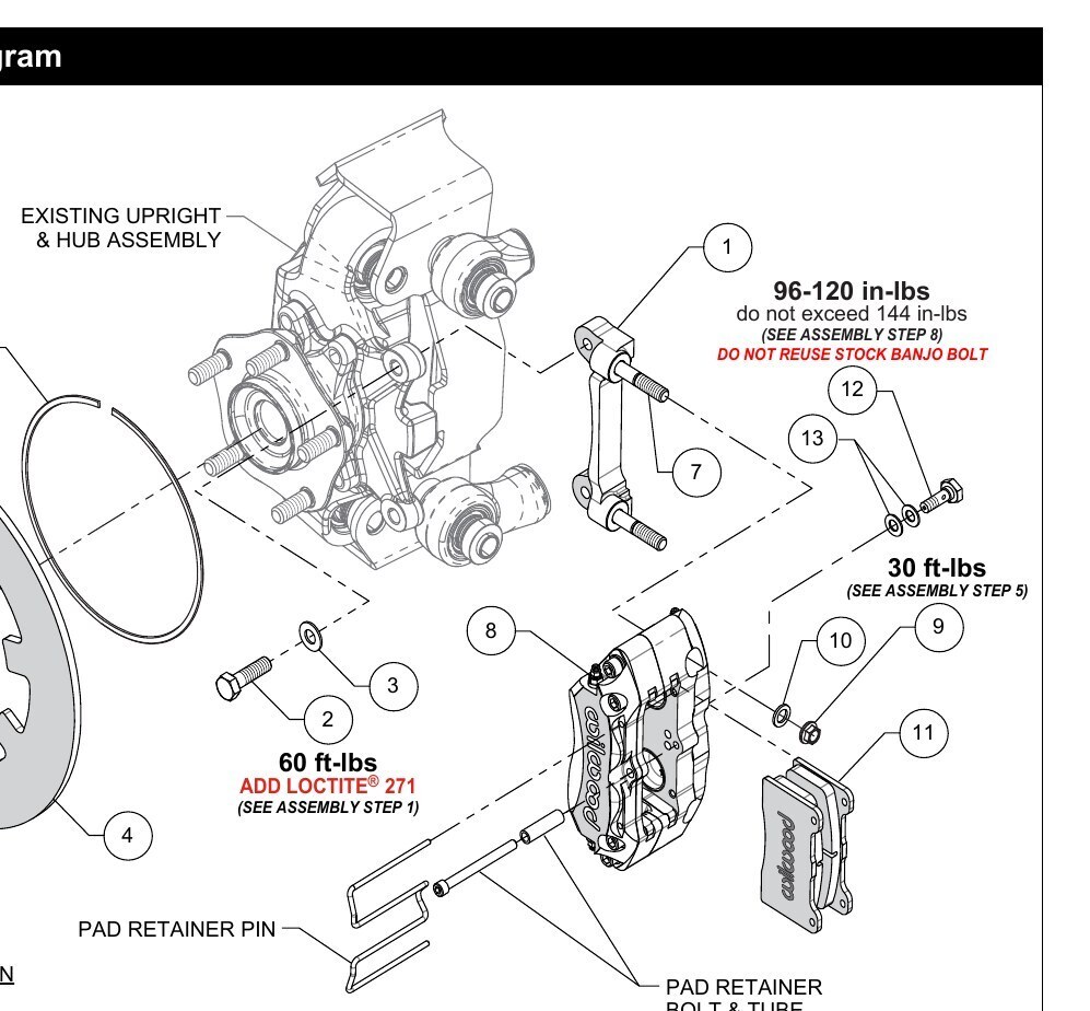
Torque Specifications
- Caliper mount bracket bolts (Item 2): 96-120 in-lbs (do not exceed 144 in-lbs); apply Loctite 271 (DO NOT REUSE STOCK BANJO BOLT)
- Hat-to-axle hub assembly fasteners (Item 1/axle nuts): 60 ft-lbs; ADD Loctite 271
- Caliper mounting (lock nuts, Item 9/10): 30 ft-lbs
- Banjo bolt (Item 12) to caliper: snug, then incrementally torque only to stop leakage without exceeding maximum specification
- Caliper utilizes a 10mm x 1.25 thread inlet (NOT the same as the OEM thread inlet 10mm x 1.00)
- This kit can be operated using the stock OEM master cylinder
- For optimum performance, fill and bleed the new system with Wilwood Hi-Temp 570 grade fluid or EXP 600 Plus. NOTE: Silicone DOT 5 brake fluid is NOT recommended for racing or performance driving.
- Test the brake pedal - should be firm; pump until firm and stop at least 1 inch from the floor under heavy load
- Bed-in pads/rotors per page 7; see Spec 37 GT series rotors note for dyno-bedded reference
- Burnish/bed-in: gradual decelerations from 55-65 MPH down to 25 MPH (light stops), then 8-10 hard decelerations from 55-65 MPH down to 25 MPH; allow brakes to cool
Installation
- The caliper mount bracket (1) should initially be installed with clean, dry threads on the mounting bolts. Orient the bracket, as shown in Figure 1 and Photo 1, and install using bolts (2) and washers (3). Temporarily tighten the mounting bolts. NOTE: The bracket must fit squarely against the mount bosses on the upright. Inspect for interference from casting irregularities, machining ridges, burrs, etc. Remove the bracket mounting bolts (2) one at a time, apply red Loctite 271 to the threads, and torque to value shown in Figure 1. NOTE: Numbers in parenthesis refer to the parts list and Figure 1 on the preceding pages.
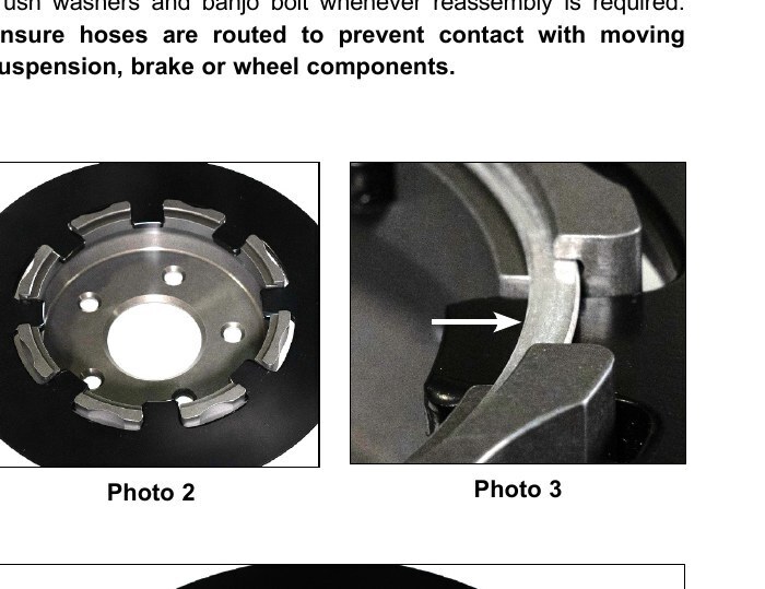
- Position the rotor (4) onto the hat (5), making sure the rotor lugs fit into the recesses of the hat, as shown in Photo 2.
- Secure rotor to the hat using the snap ring (6) by installing the ring into the groove in the hat, as shown in Photos 3 and 4. Carefully inspect snap ring to ensure complete engagement in the groove.
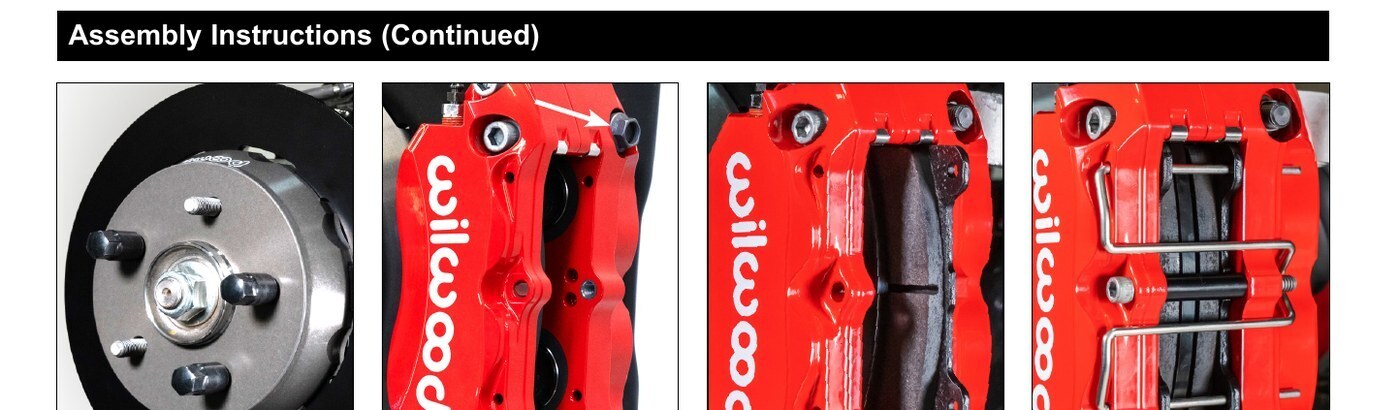
- Slide the hat/rotor assembly onto the axle hub. NOTE: The hat must fit flush against the axle hub flange or excessive rotor run out may result. Install three lug nuts to keep the hat/rotor assembly in place while continuing with the installation, Photo 5.
- Mount the caliper (8) onto the rotor (4) using lock nuts (9) and washers (10), Figure 1 and Photo 6. Torque to value shown in Figure 1.
- Remove the pad retainer clip from the caliper (8). Insert the brake pads (11) into the caliper with the friction material facing the rotor, as shown in Photo 7. Secure the pads in place using the pad clip retainer as well as the pad retainer tube and bolt, Photo 8. The bolt should be snug without play in the tube. Be cautious not to over tighten.
- Temporarily install the wheel and torque the lug nuts to the manufacturer's specification. Ensure that the wheel rotates freely without any interference. Remove wheel for next step. NOTE: The caliper in this brake kit utilizes a 10mm x 1.25 thread inlet, NOT the same as the Original Equipment Manufacturer (OEM) thread inlet (10mm x 1.00). The new banjo bolt supplied with this kit must be used.
- Attach brake line to caliper. Connect OEM brakeline to caliper using banjo bolt (12) and crush washers (13). Do not use lubricant or thread sealant on banjo bolt (12). Torque to minimum value shown in Figure 1. Check for leakage; increasing torque only to stop leakage without exceeding maximum specification. Replace crush washers and banjo bolt whenever reassembly is required. Ensure hoses are routed to prevent contact with moving suspension, brake or wheel components.
- Bleed the brake system, referring to the Additional Information and Recommendations on page 6 for proper bleeding instructions. Check system for leaks after bleeding. CAUTION: In absence of specific instructions for brake line routing, the installer must use his best professional judgment on correct routing and retention of lines to ensure safe operation. It is the installer's responsibility to ensure that all fittings and hoses are the correct size and length, properly seal, and that they will not be subject to crimping, strain, and abrasion from vibration or interference with suspension components, brake rotor or wheel.
- Install the wheel and torque the lug nuts to manufacturer's specifications. CAUTION: Test vehicle brake system per the "Minimum Test Procedure" stated within this document before driving. After road testing, inspect for leaks and interference. Initially after install and testing, perform frequent checks of the vehicle brake system and lines before driving, to confirm that there is no undue wear or interference not apparent from the initial test. Afterwards, perform periodic inspections for function, leaks and wear in an interval relative to the usage of vehicle.
- Bed-in the brake pads per the procedure on page 7.