Assembly instructions for the Wilwood UTV6 Front Brake Kit (or UTV6 Front Race Brake Kit) with 11.25" diameter dynamic mount lug-drive non-vented rotors for the 2016-2021 Polaris RZR XP Turbo & XP 4 Turbo. This kit is a direct bolt-on for factory, un-modified vehicles and is designed to work with stock OEM wheel studs.
WarningDisc brakes should only be installed by someone experienced and competent in the installation and maintenance of disc brakes. READ ALL WARNINGS.
What's in the Box
WarningWARNING: It is the responsibility of the person installing any brake component or kit to determine the suitability of the component or kit for that particular application. If you are not sure how to safely use this brake component or kit, you should not install or use it. Do not assume anything. Improperly installed or maintained brakes are dangerous. If you are not sure, get help or return the product. You may obtain additional information and technical support by calling Wilwood at (805) 388-1188, or visit our web site at www.wilwood.com. Use of Wilwood technical support does not guarantee proper installation. You, or the person who does the installation, must know how to properly use this product. It is not possible over the phone to understand or foresee all the issues that might arise in your installation.
WarningRacing equipment and brakes must be maintained and should be checked regularly for fatigue, damage, and wear.
WarningWARNING: DO NOT OPERATE ANY VEHICLE ON UNTESTED BRAKES! SEE MINIMUM TEST PROCEDURE WITHIN. Always utilize safety restraint systems and all other available safety equipment while operating the vehicle.
ImportantIMPORTANT - Read the disclaimer of warranty included in the kit.
NoteNOTE: Some cleaners may stain or remove the finish on brake system components. Test the cleaner on a hidden portion of the component before general use.
ImportantImportant: This Wilwood brake kit is designed to work with stock OEM wheel studs. The use of aftermarket wheel studs may not work with this kit.
WarningIt is the responsibility of the purchaser and installer of this kit to verify suitability / fitment of all components and ensure all fasteners and hardware achieve complete and proper engagement. Improper or inadequate engagement can lead to component failure.
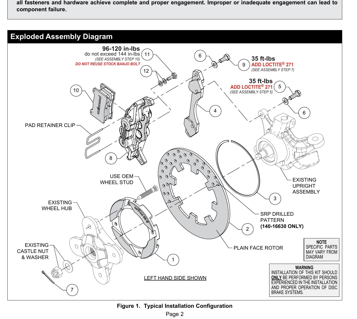
WarningWARNING (Exploded Assembly Diagram): Installation of this kit should be performed by persons experienced in the installation and proper operation of disc brake systems.
ImportantIMPORTANT (Wheel stud bolt): do not exceed 144 in-lbs. DO NOT REUSE STOCK BANJO BOLT.
ImportantIMPORTANT: Wheel stud will be reused in the following step. This Wilwood brake kit is designed to work with stock OEM wheel studs. The use of aftermarket wheel studs may not work with this kit.
WarningDo not use lubricant or thread sealant on banjo bolt (11). Torque to minimum value shown in Figure 1. Check for leakage, increasing torque only to stop leakage without exceeding maximum specification. Replace crush washers and banjo bolt whenever reassembly is required. Ensure hoses are routed to prevent contact with moving suspension, brake or wheel components.
CautionCAUTION: In absence of specific instructions for brake line routing, the installer must use his best professional judgment on correct routing and retention of lines to ensure safe operation. It is the installer's responsibility to properly route and provide adequate clearance and retention for brake hose components. It is also the installer's responsibility to ensure that all fittings and hoses are the correct size and length, properly seal, and that they will not be subject to crimping, strain and abrasion from vibration or interference with suspension components, brake rotor or wheel.
CautionCAUTION: Test vehicle brake system per the 'Minimum Test Procedure' stated within this document before driving. After road testing, inspect for leaks and interference. Initially after install and testing, perform frequent checks of the vehicle brake system and lines before driving, to confirm that there is no undue wear or interference not apparent from the initial test. Afterwards, perform periodic inspections for function, leaks and wear in a interval relative to the usage of vehicle.
WarningWARNING - DO NOT DRIVE ON UNTESTED BRAKES. BRAKES MUST BE TESTED AFTER INSTALLATION OR MAINTENANCE. MINIMUM TEST PROCEDURE: Make sure pedal is firm: Hold firm pressure on pedal for several minutes, it should remain in position without sinking. If pedal sinks toward floor, check system for fluid leaks. DO NOT drive vehicle if pedal does not stay firm or can be pushed to the floor with normal pressure. At very low speed (2-5 mph) apply brakes hard several times while turning steering from full left to full right, repeat several times. Remove the wheels and check that components are not touching, rubbing, or leaking. Carefully examine all brake components, brake lines, and fittings for leaks and interference. Make sure there is no interference with wheels or suspension components. Drive vehicle at low speed (15-20 mph) making moderate and hard stops. Brakes should feel normal and positive. Again check for leaks and interference. Always test vehicle in a safe place where there is no danger to (or from) other people or vehicles. Always wear seat belts and make use of all safety equipment.
NoteNOTE (Bedding): NEVER allow the contact surfaces of the pads or rotors to be contaminated with brake fluid. Always use a catch bottle with a hose to prevent fluid spill during all brake bleeding procedures.
NoteNOTE: With the installation of after mark of disc brakes, the wheel track may change depending on the application. Check your wheel offset before final assembly.
NoteNOTE: Silicone DOT 5 brake fluid is NOT recommended for racing or performance driving.
NoteNOTE: When using a new master cylinder, it is important to bench bleed the master cylinder first.
Diagrams & Reference
Torque Specifications
- Wheel stud bolt (Item 1, see Assembly Step 1): tighten to 96-120 in-lbs, do not exceed 144 in-lbs; DO NOT REUSE STOCK BANJO BOLT
- Bracket mounting bolts (Item 6, see Assembly Step 5): 35 ft-lbs, ADD LOCTITE 271
- Caliper mounting bolts (Item 5, see Assembly Step 7): 35 ft-lbs, ADD LOCTITE 271
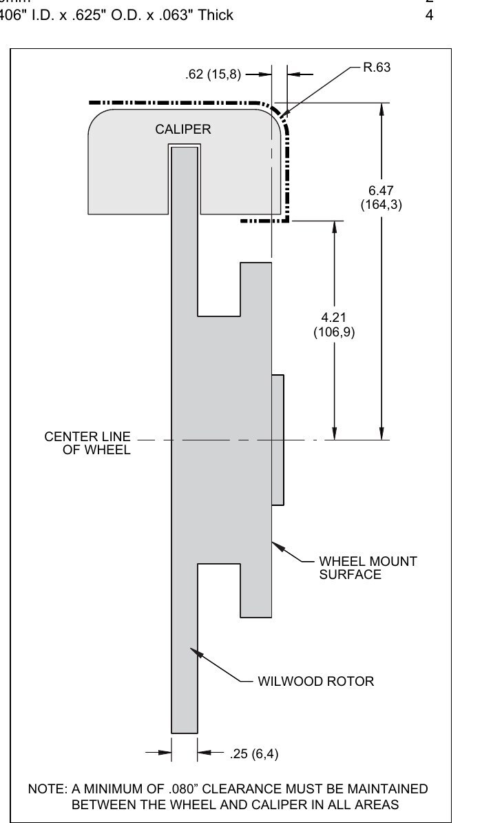
- Wheel clearance (Figure 2): A minimum of .060" clearance must be maintained between the wheel and caliper in all areas
- Wheel Clearance Diagram dimensions (Figure 2): R.63, R.43, .62 (15.8), 6.47 (164.3), 4.21 (106.9), 25 (6.4)
- Banjo bolt (Item 11): torque to minimum value shown in Figure 1; do not use lubricant or thread sealant; increase torque only to stop leakage without exceeding maximum specification
- Lug nuts: torque to the manufacturer's specification
- Caliper brake line inlet: utilizes a 10mm x 1.25 thread inlet (NOT the same as OEM caliper thread inlet 10mm x 1.00)
Installation
- Press out the OEM wheel studs from the wheel hub. Remove the front wheels, calipers, wheel hubs, and rotors. IMPORTANT: Wheel stud will be reused in the following step. This Wilwood brake kit is designed to work with stock OEM wheel studs. The use of aftermarket wheel studs may not work with this kit.
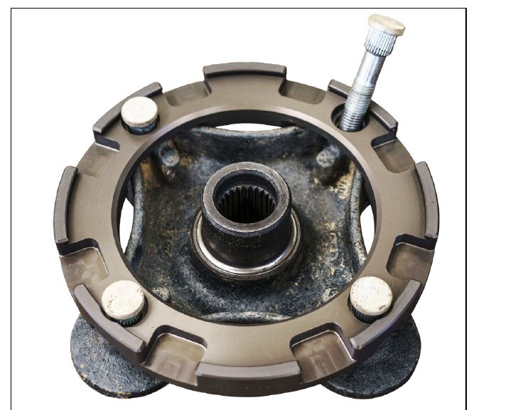
- Place the existing OEM wheel hub face down and position the rotor adapter (1) onto the wheel hub as shown in Photo 1. NOTE: The existing wheel hub must be free of dirt and debris or excessive rotor run out may result. Press the OEM wheel studs back in through the rotor adapter and OEM wheel hub.
- Position the rotor (2) onto the rotor adapter (1), making sure the rotor lugs fit into the recesses of the rotor adapter, as shown in Photo 2.
- Secure rotor to the rotor adapter using the snap ring (3) by simultaneously pushing down on the rotor and installing the ring into the groove in the rotor adapter, as shown in Photos 3 and 4. Carefully inspect snap ring to ensure complete engagement in the groove.
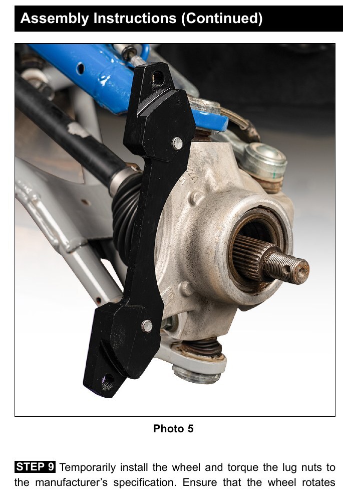
- Orient the caliper mounting bracket (4), as shown in Figure 1 and Photo 5. Install using bolts (5) and washers (6). Apply red Loctite 271 to the bolt threads and torque to value shown in Figure 1.
- Grease the splines and outer snout of the existing wheel hub with high temperature grease and slide the wheel hub/rotor assembly onto the axle, Photo 6. Attach using the existing OEM washer and castle nut. Tighten to OEM specifications and secure using cotter pin (7), Photo 7.
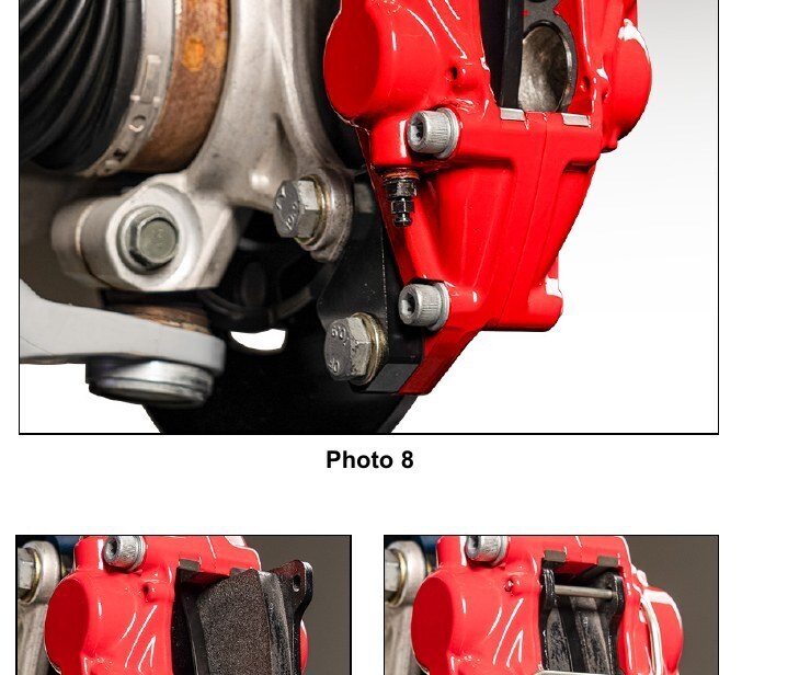
- Secure the caliper (8) to mounting bracket (4) using bolts (9) and washers (6). Apply red Loctite 271 to the threads, and torque to value shown in Figure 1.
- Remove the pad retainer clip from the caliper (8), Figure 1. Insert the brake pads (10) into the caliper with the friction material facing the rotor, as shown in Photo 9. Reinstall the pad retainer clip, Photo 10.
- Temporarily install the wheel and torque the lug nuts to the manufacturer's specification. Ensure that the wheel rotates freely without any interference. Remove wheel for next step. NOTE: The caliper in this brake kit utilizes a 10mm x 1.25 thread inlet, NOT the same as the Original Equipment Manufacturer (OEM) caliper thread inlet (10mm x 1.00). The new banjo bolt supplied with this kit must be used.
- Attach brake line to caliper. Orient OEM brake line as shown in Photo 11 and connect to caliper using banjo bolt (11) and crush washers (12). Do not use lubricant or thread sealant on banjo bolt (11). Torque to minimum value shown in Figure 1. Check for leakage, increasing torque only to stop leakage without exceeding maximum specification. Replace crush washers and banjo bolt whenever reassembly is required. Ensure hoses are routed to prevent contact with moving suspension, brake or wheel components. CAUTION: In absence of specific instructions for brake line routing, the installer must use his best professional judgment on correct routing and retention of lines to ensure safe operation. It is the installer's responsibility to properly route and provide adequate clearance and retention for brake hose components. It is also the installer's responsibility to ensure that all fittings and hoses are the correct size and length, properly seal, and that they will not be subject to crimping, strain and abrasion from vibration or interference with suspension components, brake rotor or wheel.
- Bleed the brake system, referring to the 'Additional Information and Recommendations' below for proper bleeding instructions. Check system for leaks after bleeding.
- Install the wheel and torque the lug nuts to manufacturer's specifications.
- Bed-in the brake pads per the procedure on page 7. CAUTION: Test vehicle brake system per the 'Minimum Test Procedure' stated within this document before driving. After road testing, inspect for leaks and interference. Initially after install and testing, perform frequent checks of the vehicle brake system and lines before driving, to confirm that there is no undue wear or interference not apparent from the initial test. Afterwards, perform periodic inspections for function, leaks and wear in an interval relative to the usage of the vehicle.