Fuel Pump Installa on 1. Remove all seats from vehicle.
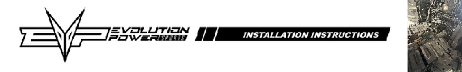
2. 4-seat: remove plas c panel under rear seats to access fuel pump. 2-seat: remove seat frame base to access fuel pump.
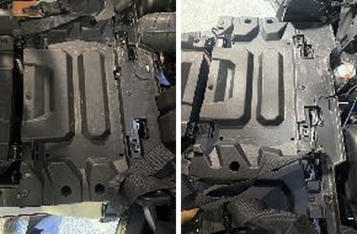
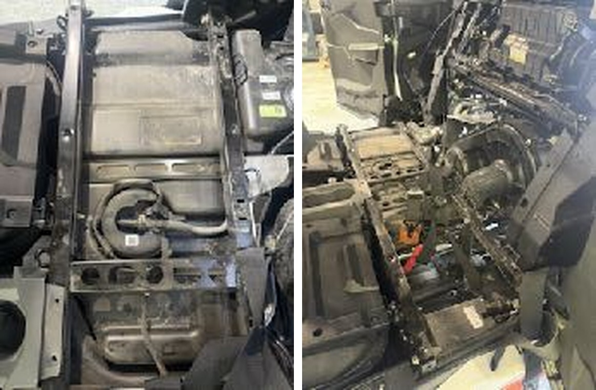
ff ti ti 3. Disconnect fuel pump connector. Remove the blue secondary lock. Carefully remove fuel line - there may be pressurized fuel s ll in the line. Unscrew fuel pump collar (normal right-hand thread). Remove OEM fuel pump assembly.
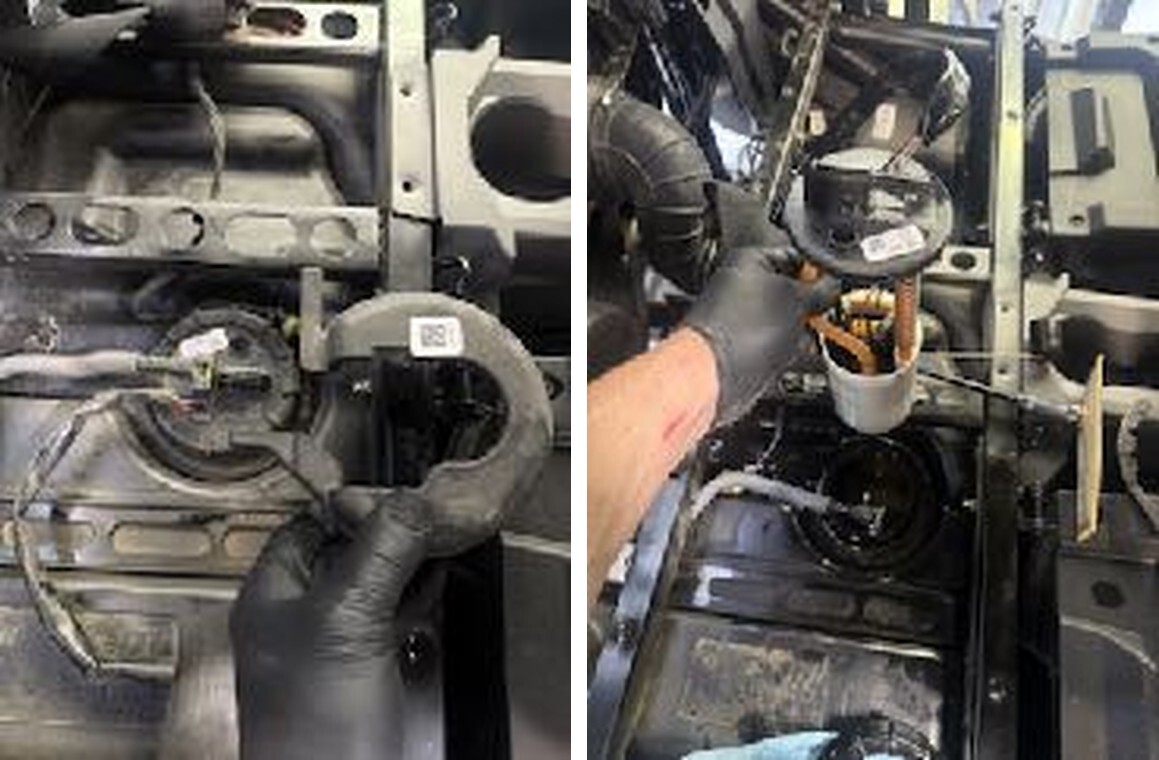
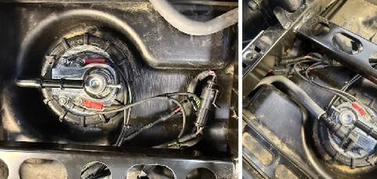
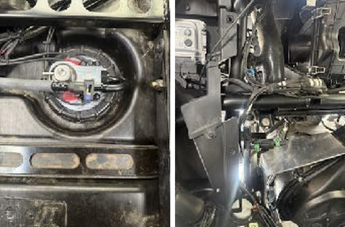
4. Transfer rubber gasket from OEM pump to EVP pump. Install new EVP fuel pump assembly. Carefully guide the siphon lter and level oat in. The lter will go toward the rear go the vehicle, the oat will go towards the front of the vehicle, and you should be able to read the logo and level/pump from the passenger side of the vehicle. Install the fuel pump collar and ghten.
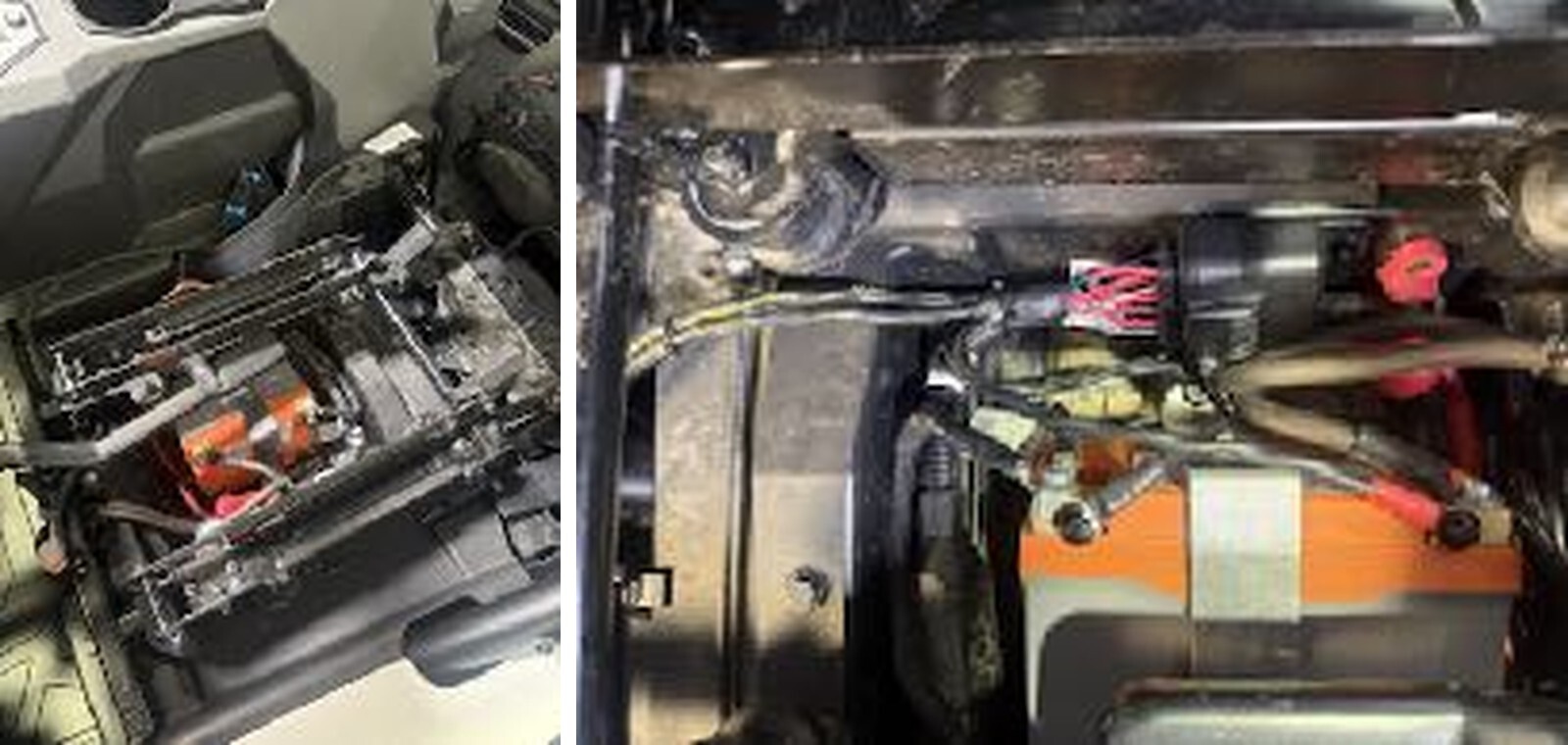
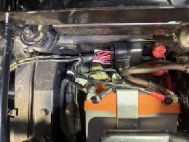
fl ti fi fl ti fi Wiring Harness Installa on 1. Star ng at the ba ery, secure the fuse/relay box near the outside (driver’s side) inside the ba ery compartment. Many vehicles have added accessories so this relay/fuse box can be bolted to the wall as photo’d or simply zip ed if there is not any extra room. Do not install the ba ery connec ons yet.
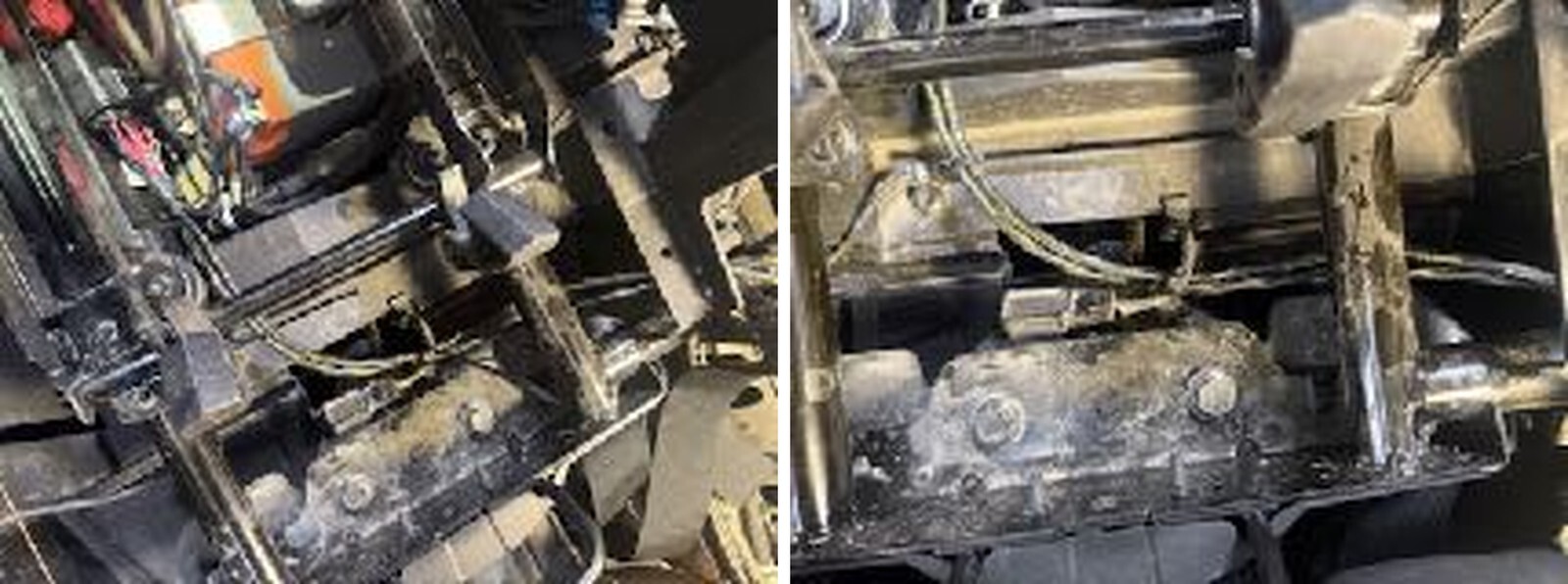
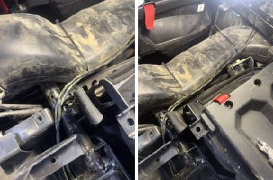
2. 4-seat models: route the harness towards the rear of the ba ery box, UNDERNEATH the seat slider, making sure the slider will not contact the harness, then towards the center of the vehicle, underneath the center console plas c, to the clutch duct. Then rearwards to the fuel pump assembly. 2-seat models: route the harness towards the rear of the ba ery box, UNDERNEATH the seat slider, making sure the slider will not contact the harness, then towards the center of the vehicle, up and over the clutch duct, out to the fuel pump. There are reliefs in the OEM center console panels the harness can pass through.
tt tt tt tt ti ti ti tt ti ti 3. Plug the OEM fuel pump connector into the new harness.
4. There are two sets of wires with eyelets. One set is small gauge wire and no ceably thinner, these are for the level side, red heat shrink will go to the + terminal. The larger gauge, thicker wires are for the pump side, red heat shrink will go to the + terminal. Do not over ghten the nuts on the studs, it will cause the nut to spin and damage the wire in the fuel pump assembly, 4 lbs max. Install the rubber nut protectors once all nuts are ght.
ft ti ti ti
7. Install the intercooler fan connector. The extension provided is for 4-seat models, or if a 2-seat requires the harness to be routed around accessories.
8. Install the ba ery terminals, red goes to posi ve, black to nega ve.
ti tti fi ti tti fi tt 9. Key on to check opera on. The fuel pump should cycle, along with the intercooler fans. It might take two key cycles to build full pressure. Check for leaks and address as needed.
ti