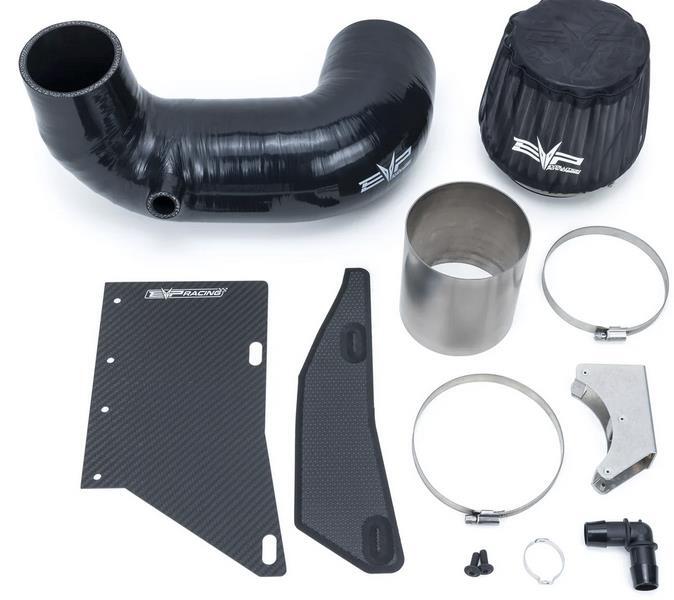
What's in the Box
Installation
1
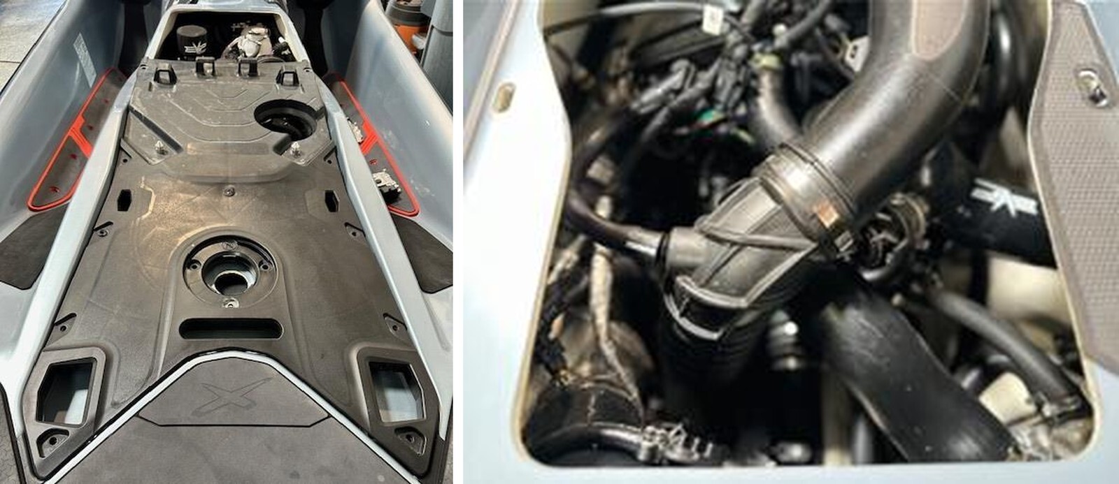
Remove seats, remove (13) T30 screws that attach the engine access panel.
2
Remove the supercharger air intake boot, plastic duct, boost recirculation hose (BRV) and crank case hose.
3
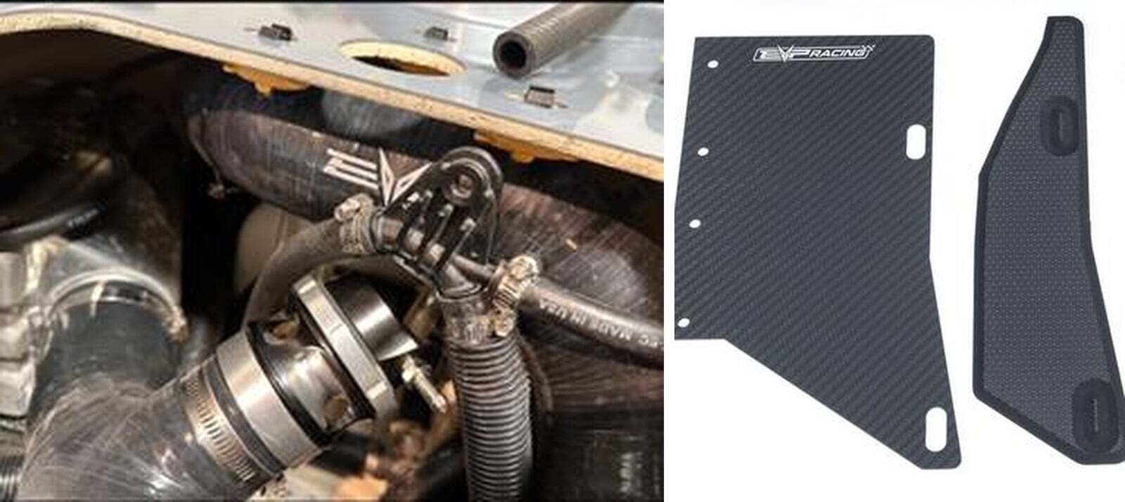
Remove the (2) hose clamps that secure the OEM 3/4" intercooler waterline at the intercooler and where this hose connects to the OEM “T” fitting.
4
Remove the (2) hose clamps that connects the OEM 1/2" water line from this same OEM “T” fitting in step 3 and where it connects to the OEM plastic water distribution block that is mounted to the OEM exhaust tube at the rear of the top deck opening. .
5
Install the supplied 3/4" and 1/2" water lines in place of the ones removed. Reuse the OEM clamps.
6
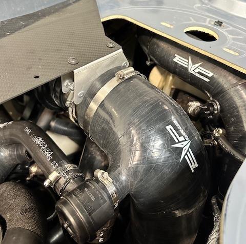
Insert the supplied titanium tube into the EVP silicone air intake tube. Leave about 2.25” of the titanium tube exposed from the end of the silicone. Secure titanium tube with supplied hose clamp.
7
Install the EVP silicone air intake tube on to the supercharger compressor inlet. Do not tighten the hose clamp at the supercharger connection. This will be done at a later step.
8
Install one of the large, supplied hose clamps into the stainless air intake support bracket. You will have to loosen the clamp entirely in order to get the clamp around the (2) mounting arms. Reinsert the end of the clamp into the screw end of the clamp and give it a few turns to capture the end of the clamp.
9
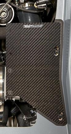
Peel and stick the supplied sea-decking on the hull as shown, make sure the (2) T-30 mounting holes are aligned. Place the carbon fiber hull mounting plate over the sea deck material and line up the hull mounting holes. To loosely hold it in place, install 2 of the OEM T-30 screws. These T30 screws are temporary and will be removed after the rest of the installation takes place.
10
Install the stainless-steel intake support bracket with clamp over the titanium tube. The orientation of the 2 mounting holes needs to be noticed before securing the intake support bracket to the carbon fiber mounting plate. Depending on RXT/RXP hull will dictate the mounting orientation / location holes on the carbon fiber plate.
11
Once you figure out your correct orientation, tighten the hose clamp to secure the stainless mounting bracket to the titanium tube. NO NOT MAKE COMPLETELY TIGHT. Only tighten enough to loosely secure it into place while still being able to move the intake support bracket on the titanium tube.
12
Install the stainless-steel mesh spark arrester / air filter to the end of the titanium tube and tighten the hose clamp. MAKE SURE there is nothing stuck inside the air filter that can get sucked into the engine / supercharger. This clamp can be final torqued.
13
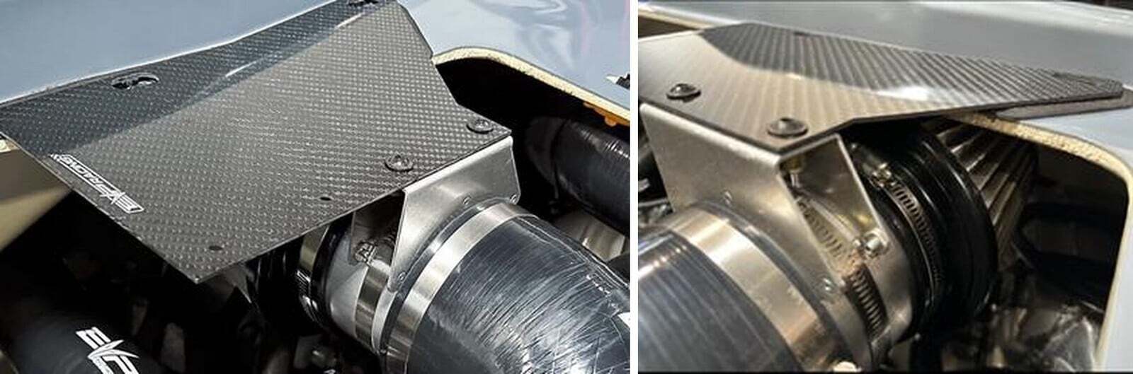
With your hand, place pressure on the carbon fiber plate and get it into position aligning the holes in the carbon plate with the holes in the hull / hull nut inserts. You can adjust the hose clamp securing the stainless-steel mounting bracket to the titanium tube while adjusting the orientation of the silicone hose in the supercharger. Since the silicone hose is wire reinforced, you can also put a bend up or down in the hose at the 90 right before the 4” opening where the titanium tube is inserted. Once everything is aligned and the carbon plate is sitting flat and holes are lined up, you can secure the supercharger hose clamp and the stainless hose clamp securing the steel mounting bracket to the titanium tube.
14
Install the OEM BRV into the 1” port on the EVP silicone intake tube and secure with the hose clamp.
15
Install the supplied 90 plastic fitting into the EVP silicone intake tube and secure with the supplied hose clamp. Install the OEM crankcase vent hose onto the plastic 90 port on the ECP silicone intake tube. Be sure to orientate the hose where it is not pinched off and secure with the hose clamp.
16
Check your work. Make sure everything is tight. Start the engine and check for leaks. You should only run the engine for 5-10 seconds.
17
Remove the temporary T30 bolts that were installed in step 9.
18
Reinstall the OEM the top engine access panel. Be sure that you start installing the T30 bolts through the hull where the carbon fiber plate is located. Loosely install these 2 x T30 bolts and tighten only a few turns. Loosely install the remaining (11) T30 bolts that were removed in step 2. After all 12 bolts are loosely started, go around and snug them tight. They don’t need to be crazy tight. They are installing into plastic nut retainers and can easily break.